Table of contents
2. Concepts related to use cases: actors, use cases, framework use cases
5. Activity diagram: concept, usage, drawing method
6. Sequence diagram: concept, purpose, drawing method
7. Collaboration diagram: concept, usage, drawing method
8. State diagram: concept, usage, drawing method
9. Package diagram: concept, purpose
10. Component diagram: concept, purpose
11. Deployment diagram: concept, purpose
12. Object diagram: concept, purpose
13. Various types of UML graphics, which ones are static views and which ones are dynamic views
1. Objects, classes, interfaces, encapsulation, inheritance, polymorphism, messages, association, combination, aggregation, dependency, implementation
(1) Object: An object is an entity in the system that describes objective things. It is a basic unit that constitutes the system. It consists of a set of attributes and a set of services that operate on this set of attributes.
(2) Class: A class is a collection of objects with the same attributes and services. It provides a unified abstract description for all objects belonging to the class. It includes two main parts: attributes and services; a class represents an abstract Concepts or affairs, objects are instances of classes that actually exist in the objective world; classes embody people’s basic thinking methods for understanding things: classification
(3) Interface: The interface describes the set of services (operations) of a class or component; the interface describes the externally visible behavior of an element
(4) Encapsulation: Encapsulation combines the properties and services of an object into an independent system unit and hides the internal details of the object as much as possible.
(5) Inheritance: Inheritance means that a child can automatically possess all the attributes and services of the parent class; inheritance is often called generalization. The public attributes and operations of the subclass belong to the base class and are shared by each subclass. Subclass inheritance Base class characteristics
(6) Polymorphism: Polymorphism means that after attributes or services defined in the parent class are inherited by the subclass, they can have different data types or show different behaviors.
(7) Message: A message is a service request issued by an object. It generally contains information such as message name, object identifier providing the service, service identifier, input information and response information.
(8) Association: This refers to the inherent involvement between transactions. In UML, it is a description of links between objects with common structural characteristics, relationships and semantics.
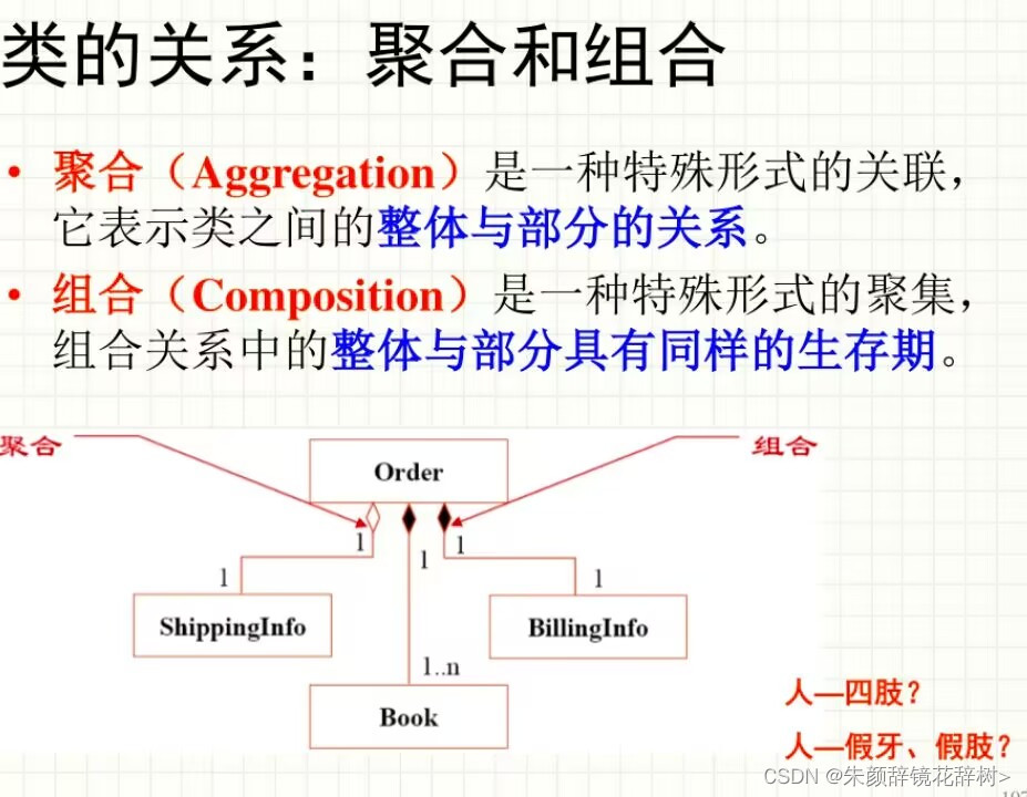
(9) Combination: It is a special form of aggregation. The whole and the parts in the combination relationship have the same survival period.
(10) Aggregation: It is a special form of association, which represents the relationship between the whole and parts of classes.
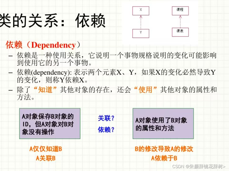
(11) Dependence: the causal relationship between two elements, where changes in one element (independent element) will affect the semantics of the other element (dependent element)
(12) Implementation: Implementation is a semantic relationship between classes. One class class specifies a contract that another class class guarantees execution.
2. Concepts related to use cases: actors, use cases, framework use cases
(1) Participants: Participants are the roles played by external entities in the interaction process with the system; participants exchange information with the software system and use the functions of the software system; participants can be either users who use the system or people who interact with the system. Other external systems, hardware devices or organizations that the system interacts with; a user plays multiple roles and requires multiple participants to represent the same user; multiple users play a unified role when using the target system and are represented by a single participant
(2) Use case: Describes the functions and behaviors visible outside the system from the user's perspective. It is a typical interaction between the participant and the target system, and does not reflect the implementation method of the function; the participant completes a certain business function with the help of the system, Or achieve a certain business goal; describe the system function as a series of events, which is a sequence of interactive actions between participants and the system. These events ultimately produce valuable observable results for participants; it can promote communication with users and understand the correct needs. , and can also be used to delineate the boundaries between the system and external entities.
(3) Framework use cases
Framework use cases refer to use cases whose macro functions are basically clear but whose content is not yet complete. The concept of framework use cases was introduced to meet the need to record and represent use cases whose details have not yet been fully determined during the requirements elicitation process. According to the abstract method of demand modeling mentioned above, first create a framework use case, cover the software demand surface as completely as possible through several framework use cases, and then fill in the details when the time is ripe, instead of completing all the details of the use case at once. This is to avoid requirements engineers getting bogged down in details prematurely and losing sight of the big picture. Of course, it is also allowed to extract other less important framework use cases after completing all the details of some key use cases.
3. Concepts related to use case diagrams: the relationship between actors and use cases, use case relationships
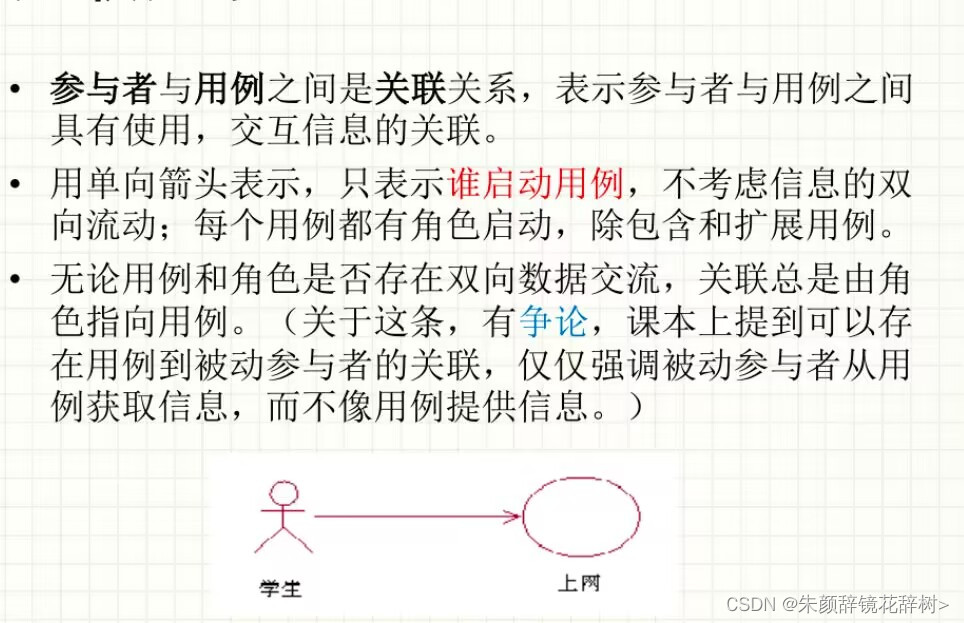
(1) The relationship between participants and use cases
① Participants trigger the execution of the use case, provide information to the use case or obtain information from the use case
②One participant ~ multiple participants, the executor who triggers the execution of the use case is called an active participant, and the executor who only obtains information from the use case is called a passive participant
③ Directed edge or undirected edge: Information transfer on a directed edge may be bidirectional; it is emphasized that passive participants only obtain information from the use case; a certain participant is the main participant of the use case
(2) Relationship between use cases
①Relationship
②Generalization relationship

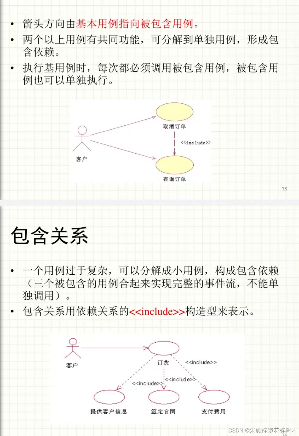
③Inclusion relationship
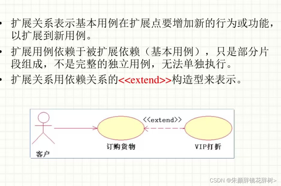
④Extended relationship
4. Class diagram: The function of class diagram, drawing method, and the relationship between classes
(1) The role of class diagram:
Class diagram describes the static structure of an object-oriented software system. The nodes of the class diagram represent the classes in the system and their attributes and operations, and the edges of the class diagram represent the relationships between classes. In the process of requirements acquisition or business understanding, class diagrams can be used to express the domain conceptual model, that is, concepts in the business domain and the relationships between concepts; in the requirements analysis stage, class diagrams can be used to represent the static structural part of the software requirements model; During the software design and implementation phases, class diagrams represent the structure and detailed design of the software. Therefore, the construction of class diagrams plays a central role in the object-oriented analysis and design process.
(2) Drawing method:
①Inheritance implementation: represented by a hollow triangular arrow.
Memory skills: 1. A hollow triangular arrow indicates inheritance or implementation.
2. The solid line represents inheritance, which is an is-a relationship, indicating expansion, not virtual, and very solid;
3. The dotted line represents realization, and the dotted line represents "virtual" without entity.
②Associated dependencies: represented by ordinary arrows.
Memory skills: 1. Dotted lines represent dependencies: used temporarily, indistinct, indistinct, if there is nothing; indicating a usage relationship, one class needs the help of another class to implement functions; generally one class takes another class as a parameter Used, or as a return value.
2. The solid line represents the association relationship: the relationship is stable, a real relationship, and a close friend; it means that one class object is related to another class object; usually one class has another class object as an attribute.
③Combination aggregation: represented by a diamond.
Memory skills: 1. The diamond shape is like a container for holding things (such as a plate);
2. Aggregation: The hollow diamond shape represents that many of the same things can be placed in the empty container and are gathered together (the class pointed in the direction of the arrow); the relationship between the whole and the part has an independent life cycle, which is a has-a relationship. ;Weak relationship, negative word: weak-empty.
3. Combination: A solid diamond represents the existence of a physical structure in the vessel, and we share life and death; the relationship between the whole and the part is stronger than the aggregation relationship; both have the same life cycle and contains-a relationship; strong relationship , positive words: strong-full.
Note: There are no solid arrows in UML class diagrams.
(3) Relationship between classes
①Conventional association

②Limited association

③Association class

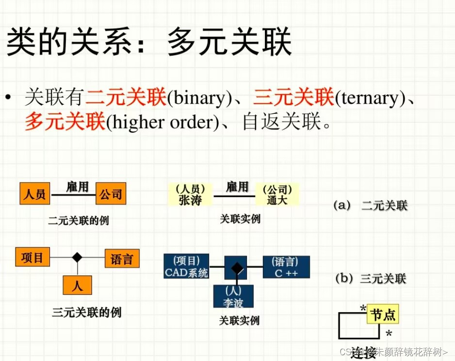
④Multiple correlations
⑤Aggregation and combination
⑥Dependence
⑦Generalization

⑧Implementation

5. Activity diagram: concept, usage, drawing method
(1) Concept: Activity diagram reflects the process from one activity to another in the system, emphasizing the control flow between objects; activity diagram describes what operation to take, what to do (object state change), and when it occurs (action sequence) , and where they occur; activity diagrams can describe concurrently executing tasks
(2) Usage: used for modeling of business processes, workflows, and complex algorithms
(3) Painting method

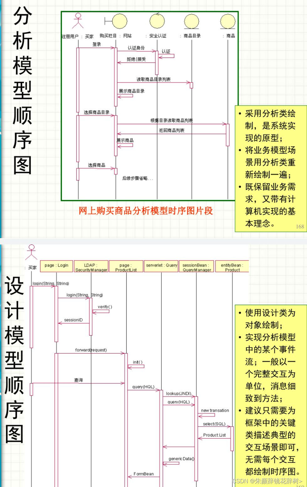
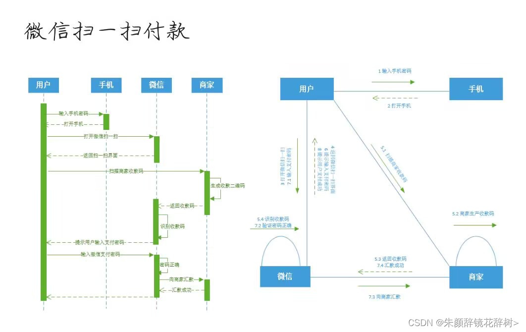
6. Sequence diagram: concept, purpose, drawing method.
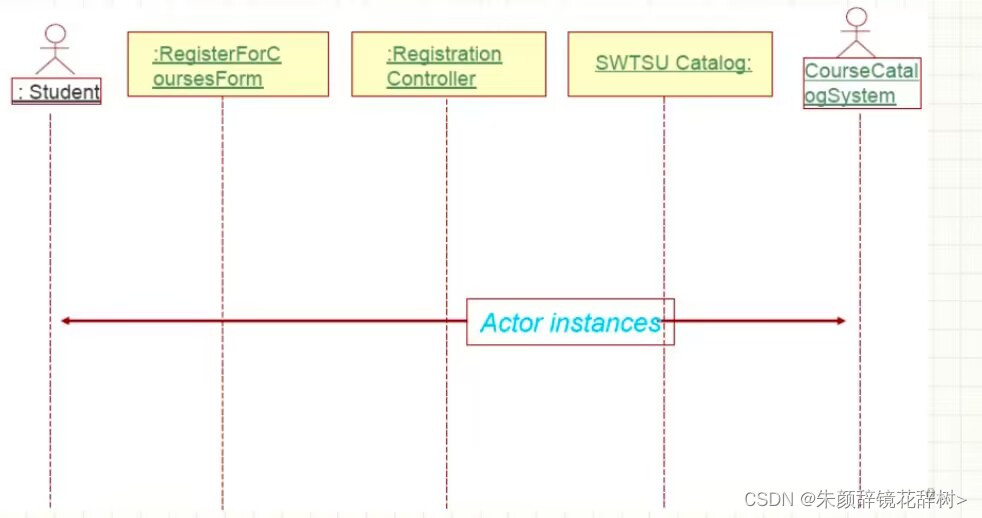
(1) Concept: A sequence diagram describes the interaction between a group of interactive objects. It represents the objects that complete a certain behavior and the time sequence of messages transmitted between these objects. Generally, we use sequence diagrams to describe - the event flow of a use case, identify the objects participating in this use case, and assign the behavior of the use case to the objects in the form of services.
(2) Purpose
1. For business personnel, sequence diagrams can show how different business objects interact, and are useful for communicating how the current business is performed. In addition to documenting the organization's current events, a business-level sequence diagram can be used as a requirements document to convey requirements for the implementation of a future system.
2. For requirements analysts, sequence diagrams can take use cases to the next level by providing a deep expression. Usually use cases are refined into one or more sequence diagrams. One of the main uses of sequence diagrams is to transform the requirements expressed by use cases into further and deeper refined expressions.
3. For technical people, sequence diagrams are very useful in recording how a future system should behave. During the design phase, architects and developers can use sequence diagrams to dig out the interactions between system objects and further improve the design of the entire system.
(3) Painting method
①General actors and objects are arranged from left to right, with the main actors on the far left
②Indicates the existence time of the object, represented by a dotted line below the object. If the object's life cycle ends, it is represented by a logout symbol.
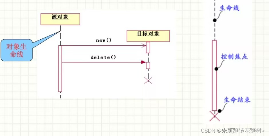
③Focus of control/activation period
A small rectangle represents the period during which the object performs an action.
The length of the focus means the length of time to perform the action

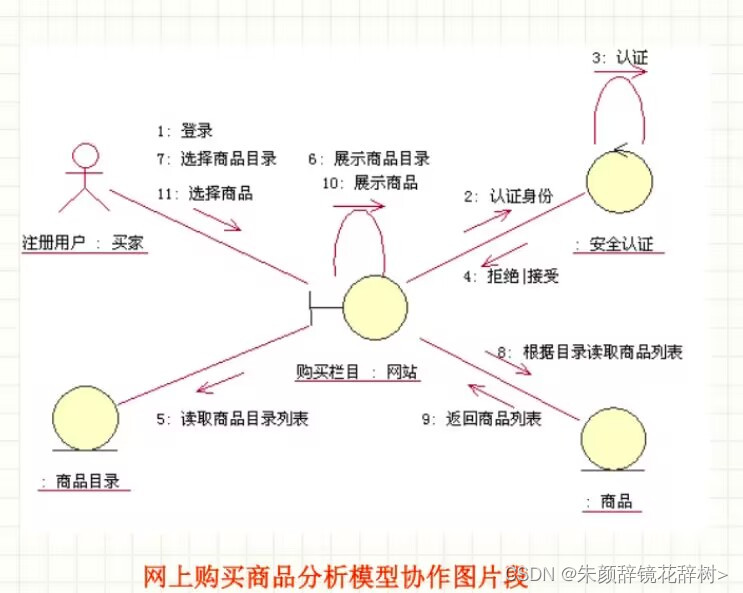
7. Collaboration diagram: concept, usage, drawing method
(1) Concept: Collaboration diagram (also called cooperation diagram and communication diagram) is another type of interaction diagram. It emphasizes the interactive relationship between objects. Indicates the location of each element in the collaboration. In a collaboration, the network structure composed of all objects in the collaboration and the overall behavior of sending messages to each other are described. Although the collaboration diagram also shows the sequence of messages, compared with the sequence diagram, it is not as clear as the sequence diagram.
(2) Usage
(3) Painting method


8. State diagram: concept, usage, drawing method
(1) Concept: The state diagram describes the reactive dynamic behavior of an entity under event stimulation. It contains all possible states of the entity, the events that can be responded to in each state, and the state changes and response actions when the event occurs. Here, the entity can be a typical object of a class, or it can be a software system (or its subpart) or one of its software components, or even the entire large system including the target software system.
(2) Usage
(3) Painting method


9. Package diagram: concept, purpose
(1) Concept: The package diagram depicts the composition and dependency relationships between packages. Among them, the package is an organizational unit of the UML model. It can contain - a group of logically associated UML model elements (such as use cases, classes, etc.), model diagrams (such as use case diagrams, class diagrams, interaction diagrams, state diagrams, activities, etc.) pictures, etc.), and other packages. Package is the basic unit of configuration management in the model management process, and also provides the basic means for access control. Throughout the software development process, package diagrams are used to organize and manage large-scale software models in a structured and hierarchical manner, minimizing mutual interference between development teams working on different packages; in the business analysis and requirements definition stages , Package diagrams can be used to describe the structure of business systems and user requirements; during the design and implementation stages, package diagrams can be used to describe the high-level structure of software systems.
10. Component diagram: concept, purpose
(1) Concept:
The component diagram describes the components in the software system and the composition relationships and dependencies between the components. It can be used in the following situations: describing the interface definitions of components in the software system and the dependencies between components in order to evaluate the scope of impact of software changes; describing the component-based design of the software system or a certain part of it, for implementation in subsequent development stages Componentized software modules establish design specifications; describe the configuration of a certain version of the software system or its part to show its internal structure.
11. Deployment diagram: concept, purpose
(1) Concept:
The deployment diagram represents the distribution of the executable artifacts of the software system in the running environment. Artifacts refer to relatively independent physical implementation units in software systems, such as dynamic link library (DLL) files under Windows platforms and class library (jar) files in Java systems. In a distributed computing environment, the deployment diagram provides a basis for software configuration management engineers to determine the packaging method for software release versions. It is also the main information source for software installation and maintenance engineers to understand the system deployment status. In addition, it is also an important reference for software design and implementation personnel to understand the software operating environment and determine the division of software components.
12. Object diagram: concept, purpose
(1) Concept: Object diagram represents a group of objects and the connections between them. It is a snapshot of the detailed state of a system at a certain moment.
(2) Purpose:
①The object diagram is essentially an instance of the class diagram.
② Object diagrams are often used to represent an instance of complex class diagrams
③ The use of object diagrams is quite limited, mainly used to express examples of data structures and to understand the specific situation of the system at a specific moment.
13. Various types of UML graphics, which ones are static views and which ones are dynamic views
(1) Static views: class diagram, object diagram, package diagram, component diagram, deployment diagram
(2) Dynamic views: activity diagrams, state diagrams, sequence diagrams, collaboration diagrams, activity diagrams