Perface
This topic introduces the 8-bit YUV color format used for video rendering .
This article describes techniques for converting between YUV and RGB formats, and also provides techniques for upsampling YUV formats.
This article is for anyone using YUV video decoding or rendering.
Introduction
There are many YUV formats defined by the video industry. This article identifies the recommended 8-bit YUV format for video rendering in Windows.
Codec vendors and display vendors are encouraged to support the formats described in this article. This article does not cover other uses of YUV colors, such as still photography.
The formats described in this article all use 8 bits per pixel position to encode the Y channel (also called the luma channel), and 8 bits per sample to encode each U or V chroma sample.
However, most YUV formats use less than 24 bits per pixel on average because they contain fewer U and V samples than Y samples . This article does not cover YUV formats with 10-bit or higher Y channels.
Note: For the purposes of this article, the term U is equivalent to Cb and the term V is equivalent to Cr.
This article covers the following topics:
- YUV sampling. Introducing the most common YUV sampling technology.
- Surface definition. Introducing the recommended YUV format.
- Color space and chroma sample rate conversion. Provides some guidelines for converting between YUV and RGB formats, and converting between different YUV formats.
- Recognize YUV format in Media Foundation. Explain how the YUV format type is described in Media Foundation.
YUV Sampling-YUV Sampling
The chroma channel can have a lower sampling rate than the luma channel without significant loss of perceptual quality. A notation called "A:B:C" is used to describe the sampling frequency of U and V relative to Y:
- 4:4:4 means the chroma channels are not downsampled.
- 4:2:2 means 2:1 horizontal downsampling and no vertical downsampling. Each scan line contains four Y samples for every two U or V samples.
- 4:2:0 means 2:1 horizontal downsampling and 2:1 vertical downsampling.
- 4:1:1 means 4:1 horizontal downsampling, no vertical downsampling. For each U and V sample, each scan line contains four Y samples. 4:1:1 sampling is less common than other formats and is not discussed in detail in this article.
The image below shows how chroma is sampled for each downsampling rate .
- Luminance samples are represented by crosses,
- Chroma samples are represented by circles.
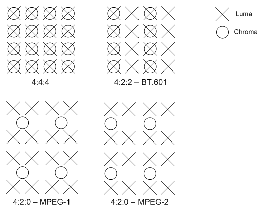
The main form of 4:2:2 sampling is defined in ITU-R recommendation BT.601.
There are two common variations of 4:2:0 sampling.
- One of them is for MPEG-2 video,
- The other is for MPEG-4 and ITU-T recommendations H.261 and H.263.
Converting between the MPEG-2 scheme and the sampling grid defined for the 4:2:2 and 4:4:4 formats is simpler than the MPEG-1 scheme .
Therefore, the MPEG-2 scheme is the preferred scheme in Windows and should be considered the default interpretation of the 4:2:0 format.
Surface definition
This section describes the 8-bit YUV format recommended for video rendering. These can be divided into the following categories:
- 4:4:4 Formats, 32 Bits per Pixel
- 4:2:2 Formats, 16 Bits per Pixel
- 4:2:0 Formats, 16 Bits per Pixel
- 4:2:0 Formats, 12 Bits per Pixel
First, in order to understand the following, you should understand the following concepts:
-
Surface origin. For the YUV format described in this article, Surface (0,0) is always the upper left corner of the Surface.
-
Stride is the width of the Surface (in bytes), sometimes called pitch. Given the Surface origin in the upper left corner, the step size is always positive.
-
Alignment Surface alignment is determined by the graphics display driver. Surfaces must always be DWORD aligned; that is, each line within the Surface must originate on a 32-bit (DWORD) boundary. However, depending on the needs of the hardware, the alignment can be larger than 32 bits.
-
Compressed format vs flat format. YUV format is divided into compressed format and flat format. In the compressed format, the Y, U and V components are stored in a single array. Pixels are organized into macropixel groups, whose layout depends on the format. In planar format, the Y, U, and V elements are stored as three separate planes.
Each YUV format described in this article has a designated FOURCC code. The FOURCC code is a 32-bit unsigned integer created by concatenating four ASCII characters.

4:4:4 Formats, 32 Bits per Pixel
AYUV
It is recommended to use a single 4:4:4 format with the FOURCC code AYUV. This is a compressed format in which each pixel is encoded as four consecutive bytes, arranged in the order shown in the image.
The byte marked A contains the value of alpha.
4:2:2 Formats, 16 Bits per Pixel
It is recommended to use two 4:2:2 formats, using the following FOURCC codes:
- YUY2
- UYVY
Both are compressed formats where each macropixel is two pixels encoded as four consecutive bytes. This results in a horizontal downsampling factor of 2 for chroma.
YUY2
In YUY2 format, the data can be viewed as an array of unsigned character values, where the first byte contains the first Y sample, the second byte contains a U(Cb) sample, and the third byte contains The second Y sample and the fourth byte contain the first V (Cr) sample as shown in the figure below.

If the image is addressed as an array of little-endian WORD values,
Then the first WORD contains the first Y sample in the least significant bit (LSB) and the first U (Cb) sample in the most significant bit (MSB).
The second WORD contains the second Y sample in LSB and the first V (Cr) sample in MSB.
YUY2 is the preferred 4:2:2 pixel format for Microsoft DirectX Video Acceleration (DirectX VA). This is expected to be a mid-term requirement for DirectX VA accelerators supporting 4:2:2 video.
UYVY
This format is identical to the YUY2 format, except that the byte order is reversed—that is, the chroma and luma bytes are flipped (Figure 4).
If the image is addressed as an array of two little-endian WORD values,
Then the first WORD contains U in the LSB and Y0 in the MSB,
The second WORD contains V in the LSBs and Y1 in the MSBs.
4:2:0 Formats, 16 Bits per Pixel
It is recommended to use two 4:2:0 16 bits per pixel (bpp) formats, using the following FOURCC codes:
- IMC1
- IMC3
Both YUV formats are flat formats.
The chroma channels are subsampled by a factor of 2 in both the horizontal and vertical dimensions.
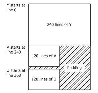
IMC1
All Y samples are first displayed in memory as an array of unsigned character values. Next are all V(Cr) samples, then all U(Cb) samples.
The V and U planes have the same step size as the Y plane, resulting in unused memory areas, as shown in Figure 5.
The U and V planes must start at a memory boundary that is a multiple of 16 rows. Figure 5 shows the origin of U and V for a 352 x 240 video frame. The starting addresses of the U and V planes are calculated as follows:
BYTE* pV = pY + (((Height + 15) & ~15) * Stride);
BYTE* pU = pY + (((((Height * 3) / 2) + 15) & ~15) * Stride);
Among them, pY is the byte pointer pointing to the starting position of the memory array, as shown in the figure below.
IMC3
This format is the same as IMC1, except that the U and V planes are swapped, as shown in the image below.
4:2:0 Formats, 12 Bits per Pixel
Four 4:2:0 12 bpp formats are recommended, using the following FOURCC codes:
- IMC2
- IMC4
- YV12
- NV12
In all these formats, the chroma channels are subsampled by a factor of 2 in both the horizontal and vertical dimensions.
IMC2
This format is the same as IMC1 except that the V (Cr) and U (Cb) lines are interleaved at half-step boundaries.
In other words, each full-stride line in the chroma region starts with a row of V samples, followed by a row of U samples, starting at the next half-stride boundary (Figure 7).
This layout utilizes address space more efficiently than IMC1. It cuts the chroma address space in half, thereby reducing the total address space by 25%.
Among the 4:2:0 formats, IMC2 is the second most preferred format after NV12. The image below illustrates this process.

IMC4
This format is the same as IMC2 except that the U(Cb) and V(Cr) lines are swapped as shown in the image below.
YV12
All Y samples are first displayed in memory as an array of unsigned character values. This array is followed by all V(Cr) samples.
The stride of the V plane is half the stride of the Y plane; and the lines contained in the V plane are half of the Y plane.
The V plane is followed by all U(Cb) samples with the same step size and number of lines as the V plane, as shown in the figure below.
NV12
All Y samples are first displayed in memory as an array of unsigned character values containing even rows.
The Y plane is followed by an array of unsigned character values containing the compressed U(Cb) and V(Cr) samples.
When the combined UV array is addressed as an array of little-endian WORD values, the LSB contains the U values and the MSB contains the V values.
NV12 is the preferred 4:2:0 pixel format for DirectX VA. It is expected to be a mid-term requirement for DirectX VA accelerators supporting 4:2:0 video. The image below shows the Y plane and the array containing the compressed U and V samples.

Conversion of color space and chroma sampling rate
This section provides guidance on converting between YUV and RGB, as well as converting between some different YUV formats.
In this section we consider two RGB encoding schemes: 8-bit computer RGB, also known as sRGB or "full-scale" RGB,
and studio video RGB, or "RGB with head-room and toe-room." They are defined as follows:
-
Computer RGB uses 8 bits for each sample of red, green, and blue. Black is represented by R=G=B=0, and white is represented by R=G=B=255.
-
Studio Video RGB uses a certain number of bits N for each sample of red, green, and blue, where N is 8 or more.
Studio video RGB uses a different scaling factor than computer RGB and has an offset. Black is represented by R=G=B=16*2 (N-8), and white is represented by R=G=C=235*2 (N-8). However, actual values may fall outside this range.
Studio Video RGB is the preferred RGB definition for video in Windows, while Computer RGB is the preferred RGB for non-video applications.
In either form of RGB, chromaticity coordinates are used for the definition of RGB primary colors as specified in ITU-R BT.709. The (x, y) coordinates of R, G and B are (0.64, 0.33), (0.30, 0.60) and (0.15, 0.06) respectively.
The reference white color is D65, and the coordinates are (0.3127, 0.3290). Nominal gamma is 1/0.45 (approximately 2.2), and precise gamma is defined in detail in ITU-R BT.709.
Conversion between RGB and 4:4:4 YUV
We first describe the conversion between RGB and 4:4:4YUV. To convert 4:2:0 or 4:2:2 YUV to RGB, we recommend converting the YUV data to 4:4:4 YUV and then converting from 4:4:4 to RGB.
The AYUV format is a 4:4:4 format, using 8 bits each for Y, U and V samples. For some applications, YUV can also be defined using more than 8 bits per sample.
Two main YUV conversions from RGB have been defined for digital video. Both are based on a specification known as ITU-R Recommendation BT.709. The first conversion is the older form of YUV defined in BT.709 for 50Hz.
It is the same relationship specified in ITU-R recommendation BT.601, also known by its old name CCIR601.
It should be considered the preferred YUV format for standard definition TV resolution (720x576) and lower resolution videos. It is characterized by the values of two constants Kr and Kb:
Kr = 0.299
Kb = 0.114
The second conversion is the newer YUV format defined in BT.709 for 60Hz and should be considered the preferred format for video resolutions above SDTV. It is characterized by the fact that the values of these two constants are different:
Kr = 0.2126
Kb = 0.0722
Conversion from RGB to YUV is defined starting from:
L = Kr * R + Kb * B + (1 - Kr - Kb) * G
The YUV values are then obtained as follows:
Y =                   floor(2^(M-8) * (219*(L-Z)/S + 16) + 0.5)
U = clip3(0, (2^M)-1, floor(2^(M-8) * (112*(B-L) / ((1-Kb)*S) + 128) + 0.5))
V = clip3(0, (2^M)-1, floor(2^(M-8) * (112*(R-L) / ((1-Kr)*S) + 128) + 0.5))
where
- M is the number of bits per YUV sample (M>=8).
- Z is a black-level variable. For computer RGB, Z is equal to 0. For studio video RGB, Z is equal to 16*2^(N-8), where N is the number of bits per RGB sample (N>=8).
- S is the scaling variable. For computer RGB, S is equal to 255. For studio video RGB, S is equal to 219*2^ (N-8).
The function floor(x) returns the largest integer less than or equal to x. The function clip3(x, y, z) is defined as follows:
clip3(x, y, z) = ((z < x) ? x : ((z > y) ? y : z))
Note: clip3 should be implemented as a function, not a preprocessor macro; otherwise the arguments will be evaluated multiple times.
Y samples represent brightness, U samples and V samples represent color deviations of blue and red respectively. The nominal range of Y is 16*2 (M-8) to 235*2 (M-8).
Black is represented as 16*2 (M-8), white is represented as 235*2 (M-8).
The nominal range of U and V is 16 2 (M-8) to 240*2 (M-8), with a value of 128 2^ (M-8) indicating neutral color.
However, actual values may fall outside these ranges.
For input data in the form of studio video RGB, clipping operations are necessary to keep U and V values in the range of 0 to (2^M)-1.
If the input is computer RGB, no clipping is required because the conversion formula cannot generate values outside this range.
These are exact formulas without approximation. Everything in this document is derived from these formulas. This section describes the following transformations:
- Converting RGB888 to YUV 4:4:4
- Converting 8-bit YUV to RGB888
- Converting 4:2:0 YUV to 4:2:2 YUV
- Converting 4:2:2 YUV to 4:4:4 YUV
- Converting 4:2:0 YUV to 4:4:4 YUV
Convert RGB888 to YUV 4:4:4
In the case of computer RGB input and 8-bit BT.601 YUV output, we believe that the formula given in the previous section can be reasonably approximated by:
Y = ( (  66 * R + 129 * G +  25 * B + 128) >> 8) +  16
U = ( ( -38 * R -  74 * G + 112 * B + 128) >> 8) + 128
V = ( ( 112 * R -  94 * G -  18 * B + 128) >> 8) + 128
These formulas produce 8-bit results using coefficients that require no more than 8 bits (unsigned) of precision. Intermediate results require up to 16 bits of precision.
Convert 8-bit YUV to RGB888
From the original RGB to YUV formula, the following relationship for BT.601 can be derived.
Y = round( 0.256788 * R + 0.504129 * G + 0.097906 * B) +  16
U = round(-0.148223 * R - 0.290993 * G + 0.439216 * B) + 128
V = round( 0.439216 * R - 0.367788 * G - 0.071427 * B) + 128
Therefore, given:
C = Y - 16
D = U - 128
E = V - 128
The formula for converting YUV to RGB can be derived as follows:
R = clip( round( 1.164383 * C                   + 1.596027 * E  ) )
G = clip( round( 1.164383 * C - (0.391762 * D) - (0.812968 * E) ) )
B = clip( round( 1.164383 * C +  2.017232 * D                   ) )
Among them, clip() means clipping to the range [0...255]. We believe these formulas can be reasonably approximated by:
R = clip(( 298 * C           + 409 * E + 128) >> 8)
G = clip(( 298 * C - 100 * D - 208 * E + 128) >> 8)
B = clip(( 298 * C + 516 * D           + 128) >> 8)
These formulas use some coefficients that require more than 8 bits of precision to produce each 8-bit result, and intermediate results will require more than 16 bits of precision.
To convert 4:2:0 or 4:2:2 YUV to RGB, we recommend converting the YUV data to 4:4:4 YUV and then converting from 4:4:4 YUV to RGB. The following sections describe some methods of converting 4:2:0 and 4:2:2 formats to 4:4:4.
Convert 4:2:0 YUV to 4:2:2 YUV
Converting 4:2:0 YUV to 4:2:2 YUV requires twice the vertical upconversion. This section describes an example method of performing upconversion. This method assumes that the video image is progressively scanned.
NOTE: The 4:2:0 to 4:2:2 interlaced conversion process has atypical problems and is difficult to implement. This article does not discuss converting interlaced scans from 4:2:0 to 4:2:2.
Let each vertical line of the input chroma sample be an array Cin[] ranging from 0 to N - 1. The corresponding vertical line on the output image will be a Cout[] array ranging from 0 to 2N - 1. To convert each vertical line, follow this procedure:
Cout[0]     = Cin[0];
Cout[1]     = clip((9 * (Cin[0] + Cin[1]) - (Cin[0] + Cin[2]) + 8) >> 4);
Cout[2]     = Cin[1];
Cout[3]     = clip((9 * (Cin[1] + Cin[2]) - (Cin[0] + Cin[3]) + 8) >> 4);
Cout[4]     = Cin[2]
Cout[5]     = clip((9 * (Cin[2] + Cin[3]) - (Cin[1] + Cin[4]) + 8) >> 4);
...
Cout[2*i]   = Cin[i]
Cout[2*i+1] = clip((9 * (Cin[i] + Cin[i+1]) - (Cin[i-1] + Cin[i+2]) + 8) >> 4);
...
Cout[2*N-3] = clip((9 * (Cin[N-2] + Cin[N-1]) - (Cin[N-3] + Cin[N-1]) + 8) >> 4);
Cout[2*N-2] = Cin[N-1];
Cout[2*N-1] = clip((9 * (Cin[N-1] + Cin[N-1]) - (Cin[N-2] + Cin[N-1]) + 8) >> 4);
Among them, clip() means clipping to the range of [0...255].
NOTE: The equations for handling edges can be mathematically simplified. They are shown this way to illustrate the clamping effect of the edges of the picture.
In practice, this method calculates each missing value by interpolating the curve over four neighboring pixels, weighted according to the value of the two nearest pixels (Figure 11). The specific interpolation method used in this example generates missing samples at half-integer positions using a well-known method called Catmull-Rom interpolation (also known as cubic convolution interpolation).
In terms of signal processing, vertical upconversion should ideally include phase shift compensation to account for the half-pixel vertical offset between the 4:2:0 sample line position and the 4:2:0 sample line position (relative to the output 4: 2:2 sampling grid). The position of the sample line is sampled every 4:2:2. However, introducing this offset increases the amount of processing required to generate the samples, and the original 4:2:0 samples cannot be reconstructed from the upsampled 4:2:2 image. It also fails to decode video directly into 4:2:2 surfaces and then use those surfaces as reference pictures to decode subsequent pictures in the stream. Therefore, the method presented here does not take into account the precise vertical alignment of the samples.
If you start from a 4:2:0 video using the sampling grid defined in H.261, H.263 or MPEG-1 video, the phase of the output 4:2:2 chroma samples will also be shifted by half - relative to Pixel horizontal offset of the luma sampling grid spacing (relative to a quarter-pixel offset of the 4:2:2 chroma sampling grid spacing). However, the MPEG-2 form of 4:2:0 video is probably more commonly used on PCs and does not suffer from this problem. Furthermore, at reasonably high image resolutions, this distinction may not be visually damaging. Attempting to correct this problem creates the same type of problem discussed with vertical phase offset.
Convert 4:2:2 YUV to 4:4:4 YUV
Converting 4:2:2 YUV to 4:4:4 YUV requires twice the horizontal upconversion. The methods previously described for vertical upconversion can also be applied to horizontal upconversion. For MPEG-2 and ITU-R BT.601 video, this method will generate samples with correct phase alignment.
Convert 4:2:0 YUV to 4:4:4 YUV
To convert 4:2:0 YUV to 4:4:4 YUV, just follow the two methods introduced earlier. Convert 4:2:0 images to 4:2:2, and then convert 4:2:2 images to 4:4:4. You can also switch the order of the two upconversion processes, since the order of operations is not important for the visual quality of the result.
Other YUV formats
Some other less common YUV formats include:
- AI44 is a toned YUV format with 8 bits per sample. Each sample contains an index in the 4 most significant bits (MSB) and an alpha value in the 4 least significant bits (LSB). The index refers to an array of YUV palette entries, which must be defined in the format's media type. This format is primarily used for subpicture images.
- NV11 is a 4:1:1 planar format with 12 bits per pixel. Y samples appear first in memory. The Y plane is followed by a compressed array of U (Cb) and V (Cr) samples. When the combined UV array is addressed as an array of little-endian WORD values, the U samples are contained in the LSB of each WORD and the V samples are contained in the MSB. (This memory layout is similar to NV12, although the chroma sampling is different.)
- Y41P is a 4:1:1 compression format that samples U and V every four pixels in the horizontal direction. Each macropixel contains 8 pixels in three bytes with the following byte layout: U0 Y0 V0 Y1 U4 Y2 V4 Y3 Y4 Y5 Y6 Y7
- Y41T Same as Y41P, except that the least significant bit of each Y sample specifies the chroma key (0 = transparent, 1 = opaque).
- Y42T is the same as UYVY, except that the least significant bit of each Y sample specifies the chroma key (0 = transparent, 1 = opaque).
- YVYU is equivalent to YUYV, except that the U and V samples are swapped.
Recognize YUV format in Media Foundation
Each YUV format described in this article has a designated FOURCC code. The FOURCC code is a 32-bit unsigned integer created by concatenating four ASCII characters.
There are various C/C++ macros that make it easier to declare FOURCC values in source code. For example, the MAKEFOURCC macro is declared in Mmsystem.h and the FCC macro is declared in Aviriff.h. Use them as follows:
DWORD fccYUY2 = MAKEFOURCC('Y','U','Y','2');
DWORD fccYUY2 = FCC('YUY2');
You can also declare a FOURCC code directly as a string literal by reversing the order of the characters. For example:
DWORD fccYUY2 = '2YUY';  // Declares the FOURCC 'YUY2'
由于 Windows 操作系统使用小端架构,因此必须颠倒顺序。“Y”= 0x59,“U”= 0x55,“2”= 0x32,因此“2YUY”为 0x32595559。
In Media Foundation, formats are identified by primary type GUID and subtype GUID. The main type of computer video format is always MMFediaType_Video. Subtypes can be constructed by mapping FOURCC codes to GUIDs as follows:
XXXXXXXX-0000-0010-8000-00AA00389B71
Where is the XXXXXXXXFOURCC code. Therefore, the subtype GUID for YUY2 is:
32595559-0000-0010-8000-00AA00389B71
The most common YUV format GUID constants are defined in the header file mfapi.h.