2. Principle of phase selection subroutine
The first step in the fault handling program logic of distance protection is to identify the fault phase, that is, phase selection. Only when the type and phase of the fault are determined can we determine which phases of current and voltage should be used in the impedance calculation. For example, the sum of BC phase faults and the sum of A phase ground faults (see Chapter 2, Section 2 for details) algorithm for solving differential equations). Obviously only the impedance value of the fault phase (between) can reflect the fault distance, so the first thing is to correctly identify the fault phase.
In conventional protection, the ground distance comprehensive reclosing device is equipped with three phase selection elements for single-phase grounding, and the phase distance protection is equipped with three phase selection elements for phase-to-phase faults. They all use three complex hardware devices to realize the phase selection function, and cannot realize switching judgment and phase selection between grounding and phase-to-phase faults. In order to realize single-phase grounding and phase-to-phase fault phase determination of high-voltage lines, conventional protection uses multiple sets of grounding and phase-to-phase protection devices to operate in parallel, resulting in numerous protection devices and complicated wiring, thereby reducing the reliability of protection. Microcomputer distance protection uses the phase-specific software switching principle to completely solve the above-mentioned difficulties in phase selection, that is, it can select phases for both grounding and phase-to-phase faults. Another advantage of this phase-specific software switching method is that for a two-phase ground short circuit, the impedance can be calculated according to the phase fault method after phase identification, thereby solving the problem of conventional ground impedance relay determination of the leading phase when two phases are grounded. A problem worth transcending.
There are many ways to select phases for microcomputer protection. Here we mainly analyze the simple and easy phase selection method for phase current difference mutation. The phase selection component of the sudden change in phase current difference uses the amplitude characteristics of the sudden change in the two-phase current difference to distinguish various types of faults when a system fault occurs. The characteristics of the two-phase current difference mutation amplitudes of various fault types are discussed below.
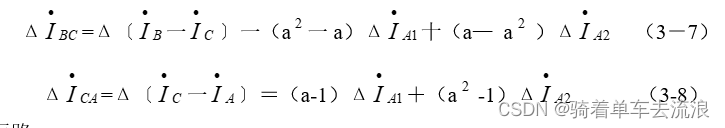
First, use the concept of symmetric component method to write the formula for the mutation amount of the two-phase current difference. If the basic vector is taken as the basic vector, then there is the following formula
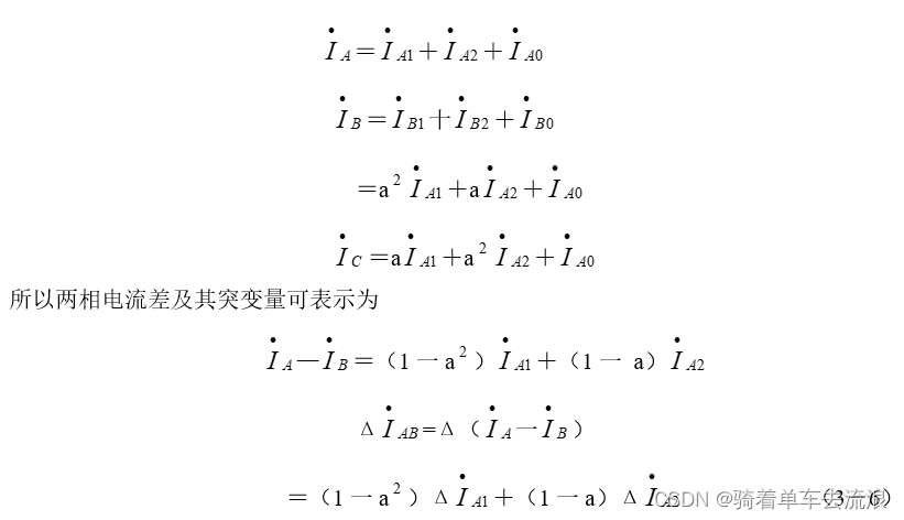
In the formula, the subscripts 1, 2, and 0 represent the positive, negative, and zero sequences of the fault respectively. You can also write other two-phase current difference mutation formulas, and finally discuss the amplitude characteristics according to fault types.
1. Single phase to ground short circuit
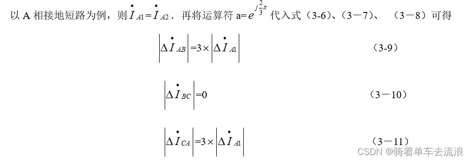
It can be seen that the largest characteristic of the amplitude of a single-phase grounding short circuit is that the mutation amount of the current difference between the two non-fault phases is zero. According to the characteristics of the two-phase current difference. Draw the phasor diagram of single-phase grounding (for example, phase A grounded), as shown in Figure 3-6(a). The two non-fault phase currents may be 180 out of phase with the fault phase current, or they may be in the same phase, which depends on the positive sequence and zero sequence impedance distribution coefficients of the system on both sides of the fault point.
2. Two-phase short circuit without grounding
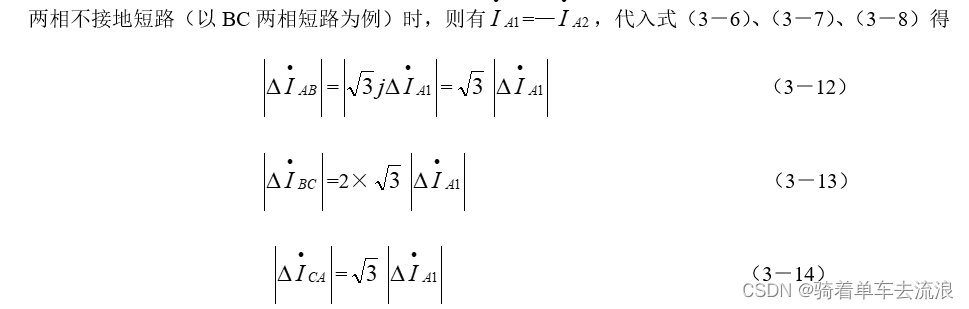
It can be seen that the amplitude characteristic of a two-phase short circuit is that the absolute value of the mutation amount of the current difference between the two fault phases is the largest. The phasor diagram of the current difference between the two fault phases is shown in Figure 3-6(b).
Two-phase grounding short circuit takes BC two-phase grounding short circuit as an example. The phasor diagram is shown in Figure 3-6 (C). At this time, among the three phase current differences, the current difference between the two fault phases is still the largest. The algorithm proves Omit.
3·Three-phase short circuit
When three phases are short-circuited, it is obvious that the absolute values of the three phase current differences are equal, and the proof and phasor diagram are omitted.
From the above analysis, it can be seen that the fault type can be easily determined by comparing the maximum and minimum absolute values of the mutation amount of the two-phase current difference, that is, the fault phase can be selected. Specifically, the simple discriminant formula (3-15) is obtained from formulas (3-9), (3-10), and (3-11). The large, medium, and small in the formula are the absolute values of the three phase current difference mutations. Sort by size.
In microcomputer protection, the judgment flow chart of the above phase selection principle is shown in Figure 3-7.
