The reference to 37 sensors and modules has been widely circulated on the Internet. In fact, there must be more than 37 sensor modules compatible with Arduino. In view of the fact that I have accumulated some sensors and modules on hand, according to the concept of practice (hands-on try), for the purpose of learning and communication, I am going to do experiments one by one here, and will record them regardless of whether they are successful or not. It is a difficult problem, and I hope to be able to throw bricks and spark jade.
[Arduino] 168 kinds of sensor module series experiment (data code + simulation programming + graphics programming)
experiment 212: 9 in 1 multi-function expansion board DHT1 device temperature and humidity LM3 temperature 5 buzzer 1 compatible with UNO

Take the combination of "Arduino program code" + "Mind + graphics programming" + "Linkboy simulation programming"
Complement each other, lay a solid foundation, and promote understanding

Experiment catalog (Arduino hands-on)
1. LED experiment
01 Blink: D13 blue LED blinks
02 Blink2: D12, D13 red and blue LEDs blink alternately
03 Blink3: Simulate flashing alarm light
04 Breath_LED: D9 full-color LED simulates red breathing light
2. Button experiment
05 Button: D2 button controls D13 blue LED
06 Button_Lock: D3 button controls D13 blue LED self-locking experiment
3. Potentiometer experiment
07 RS232_AD: serial port reads A0 potentiometer to collect value (rotation angle 270° output 0 -3.3V/5V voltage signal potentiometer resistance value 10K)
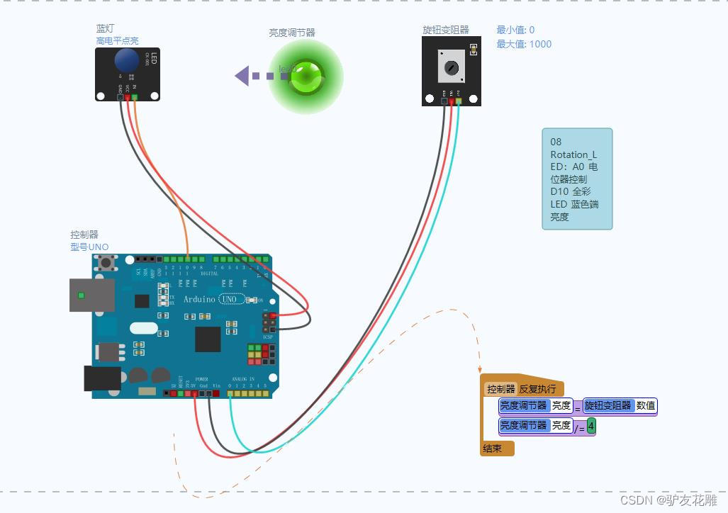
08 Rotation_LED: A0 potentiometer controls D11 full-color LED blue terminal brightness
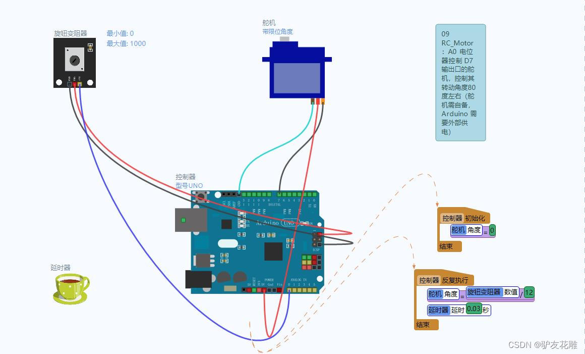
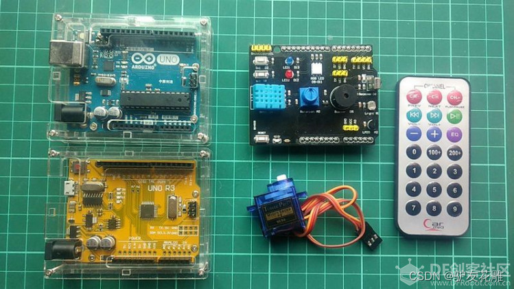
09 RC_Motor: A0 potentiometer controls the steering gear at the output port of D7 to control its rotation angle (the steering gear needs to be automatically Arduino needs external power supply)
4. RGB full-color LED experiment
10 LED_RGB_Text: full-color LED basic color change
11 LED_RGB: full-color LED rainbow change
5. Infrared sensor D6 experiment (infrared remote control needs to be prepared by yourself)
12 IRrelay: press infrared remote control Any key of the device can control the D13 LED switch (control distance 1-8 meters, frequency 38KHz, compatible with most infrared remote controls on the market)
13 IRrecord: The serial port displays the read infrared remote control code
6. Temperature sensor experiment
14 LM35_RS232AD: The serial port
displays the temperature read by the LM35 temperature sensor on the A2 port (it can test the indoor and outdoor temperature, the range is -50-150°C, and the sensitivity is good).
Taken temperature and humidity data (temperature measurement range 0-50°C, humidity range 20%-90%PH)
8. Brightness sensor experiment
16 Light Sensor: serial port displays the value collected by the photoresistor of port A1
17 Light_LED: control of the photoresistor of port A1 D13 LED switch (sensitive to light, suitable for teaching experiments and civilian equipment)
9. Buzzer experiment
18 Buzzer: D5 port passive buzzer to simulate an ambulance siren (can make simple music sounds, music needs to be programmed)
10 , Extended experiment
19 Analog ultrasonic ranging sensor (detection type I, IIC/I2C interface)
20 Bus DS18B20 temperature sensor (numeric type, connected to the digital D7 interface of the expansion board)
21 TM1637 four-digit digital tube (digital tube and dot matrix type, connected to Expansion board digital D7/D8 interface)
22 GY-BMP280-3.3 Atmospheric pressure altimeter sensor module (numeric type, IIC/I2C interface)
23 GY-NEO-6MV2 new flight control GPS satellite signal receiving module (numeric type, TTL interface)
24 5V low-level trigger single-channel relay module (executive type, digital D7 interface)
25 4-wire sound sensor module with electret microphone (trigger type, digital D7 interface)
26 BH1750FVI digital light intensity module light sensor (numeric type, IIC/ I2C interface)
27 Open source DFPlayer Mini TF card MP3 player module (output actuator type D7/D8 digital interface)
28 LCD1602 LCD screen module (output display type, IIC/I2C interface)
29 Human body infrared pyroelectric motion sensor module (trigger type, digital D7 interface)
30 DS1307 clock module Tiny RTC I2C module (detection sensor type, IIC/I2C interface)
31 compatible HC-06 slave Bluetooth module (communication and storage type, TTL interface)

3. Potentiometer experiment
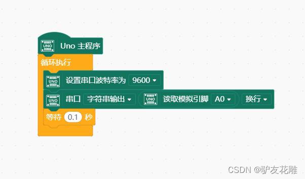
07 RS232_AD: serial port reading A0 potentiometer to collect value (rotation angle 270° output 0-3.3V/5V voltage signal potentiometer resistance 10K) 08
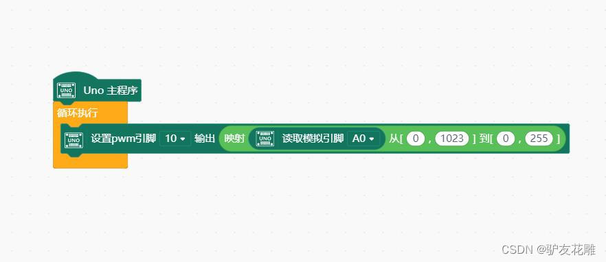
Rotation_LED: A0 potentiometer control D11 full-color LED blue terminal Brightness
09 RC_Motor: A0 potentiometer controls the steering gear at the D7 output port to control its rotation angle (the steering gear needs to be equipped with Arduino and needs external power supply)
07 RS232_AD: Serial port reading A0 potentiometer to collect values (rotation angle 270° output 0-3.3V/5V voltage signal potentiometer resistance 10K)
Arduino experiment open source code
/*
Eagler8实验程序列表
07 RS232_AD:串口读取 A0 电位器采集的数值(旋转角度270°,输出0-3.3V/5V电压信号,电位器阻值10K)
*/

void setup()
{


  Serial.begin(9600); // 打开串口,设置波特率为9600 bps
}
void loop()
{


      int val;
      val=analogRead(0);   //传感器接于模拟口0
      Serial.println(val,DEC);//从串口发送数据并换行
      delay(100);
}


08 Rotation_LED: A0 potentiometer controls D10 full-color LED blue end brightness
Arduino experiment open source code
/*
Eagler8实验程序列表
08 Rotation_LED:A0 电位器控制 D10全彩 LED 蓝色端亮度
*/

void setup()
{


  pinMode(10,OUTPUT);
}

void loop()
{


  int n = analogRead(A0);
  analogWrite(10,n/4);
}
09 RC_Motor: A0 potentiometer controls the steering gear at the D7 output port to control its rotation angle (the steering gear needs to be provided by itself, and the Arduino needs an external power supply)
Arduino experiment open source code
/*
Eagler8实验程序列表
09 RC_Motor:A0 电位器控制 D7 输出口的舵机,控制其转动角度(舵机需自备,Arduino 需要外部供电)
*/

#include <Servo.h>
Servo myservo;

int analogPin = 0;

int val;
void setup()
{


  myservo.attach(7);  // 7号引脚输出电机控制信号

  Serial.begin(9600);
}
void loop()
{


  Serial.print("servo:");
  Serial.println(val);
  delay(15);
  val = analogRead(analogPin);       // 读取来自可变电阻的模拟值(0到1023之间)
  val = map(val, 0, 1023, 0, 179);   // 利用“map”函数缩放该值,得到伺服电机需要的角度(0到180之间)

  myservo.write(val);   // 设定伺服电机的位置

  delay(15);            // 等待电机旋转到目标角度
}