Embedded Development – CubeMX Getting Started Tutorial
Introduction to CubeMX
When developing a traditional single-chip microcomputer, it is necessary to do various initialization work for the on-chip peripherals, which is quite troublesome.
CubeMX is a graphical code generation tool produced by ST Company. Through the graphical interface, you can intuitively configure the parameters of various on-chip peripherals, clocks, interrupts, DMA, etc., and then CubeMX can directly generate initialization Code, so that developers can focus more on the development of core code.
The generated code is selectively adapted to IAR, KEIL, and ST's own STM32CubeIDE (free)
initial interface
This is the interface after opening the software
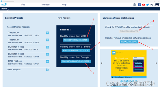
On the far left is the previously opened project, in the middle is the way to generate a new project, and on the right is the software installation option.
Follow the arrows to explain:
1: Generate a project by selecting an MCU, which is generally used.
2: Generate a project by selecting an ST development board. For those who have an ST development board and want to learn the development board routines, you can choose this.
3: Generate a project through an example. This example is the name of the routine that the development board has implemented. For example, if I want to learn the SPI interface, then I can open it through this, and then select the ST development board, which is the same as item 2. .
4: Check for updates
5: Install and remove packages. Each MCU needs to install the corresponding support package. You can install , delete or update the package from here.
generate project
Next, we generate a project for calculating CRC. The chip used is STM32G030C8T6, and PA9 and PA10 are configured as serial ports. Enable the serial port interrupt. External crystal oscillator 8MHz. Will use KEIL for software development in the future.
Click the arrow 1 to come to the MCU model selection interface
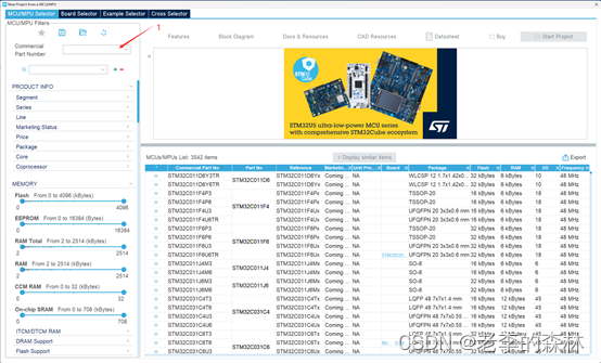
Enter STM32G030C8T6 at 1, and the previous STM32 may not be entered. As we input, the right window will gradually narrow the selection range, as shown in the figure below, note that the keyboard must be in the English input state, and the Chinese state is not acceptable .
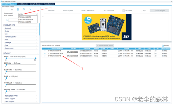
The chip pointed by arrow 2 is what we want to choose.
At the same time, information such as reference unit price, chip package, FLASH and RAM capacity, number of IO ports and maximum frequency are also given to facilitate our selection. After confirming the
chip, double-click it to enter the next interface.
Function configuration interface
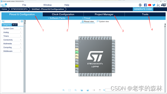
It contains 4 tabs, let's introduce them one by one.
1 Pins and configuration
This interface is the most commonly used, on the left is to configure the MCU core, on-chip peripherals, and middleware.
On the right side, you can configure the IO port and pin multiplexing function.
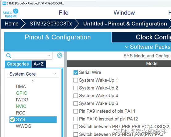
Next, we click on System Core, click SYS, and check the first item Serial Wire in the new window that appears, which means to enable the SWD debugging interface, that is, through the simulation Downloader and debugger.
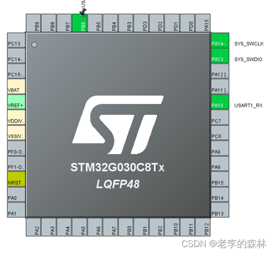
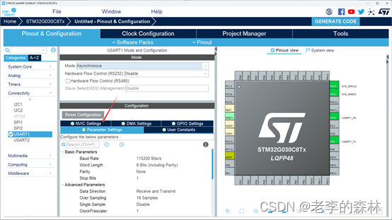
Click Connectivity, click USART1, and select Asynchronous for Mode, which means asynchronous serial port. Others remain default. In the window below, the communication speed can be set as required, the default is 115200bps, 8 data bits, no parity, 1 stop bit

At this point, you can see that the relevant pins have turned green on the right side of the window. It can be seen that PA9 is the TX pin and PA10 is the RX pin.
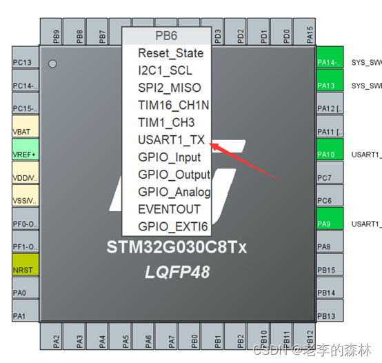
If PA9 must be used for other functions, there is still a spare pin to choose. The method is to hold down Ctrl, and then press and hold PA9 with the left mouse button. At this time, the spare pin will start to flash. There is only one spare pin for this chip: Left click on PB6
and select USART1_TX to change the pin to TX function
configuration interrupt
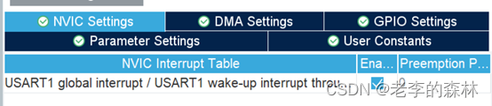
Click on the NVIC Settings pointed by the red arrow
Check the box to enable the serial port interrupt
Turn on the CRC module
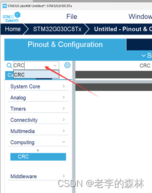
The CRC function is configured in Computing, but if you don’t know it, how can you quickly find it?
Enter the CRC at the place indicated by the arrow, and press Enter. Note that the input must be in English , and the configuration item of Computing to which the CRC belongs will appear in the lower left
Check the arrow below to activate the CRC module
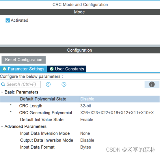
The following parameters are set as desired.
You can set the length, polynomial, initial value, whether the input is reversed, whether the output is reversed, etc.
After setting, directly send the array to be calculated to the CRC calculation unit, that is, use the HAL_CRC_Calculate() function, and the return value is the CRC value we want to calculate, which is convenient and quick.
If there is hardware available, there is no need to write functions, which is faster and saves space.
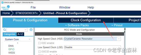
clock configuration
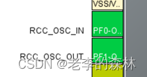
Select HSE as the external clock in RCC, that is, Crystal, which means external crystal oscillator. The following two pins are the crystal oscillator pins, which will turn green.
Click the red arrow below to configure the clock
Select the clock route in the figure below
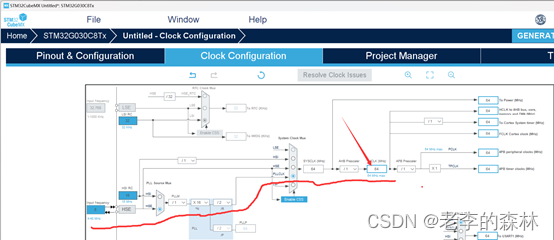
Enter 64 at the arrow and press Enter, which means to use the main frequency of 64M, and the related multiplier and frequency division parameter software will automatically calculate it for us.
generate code
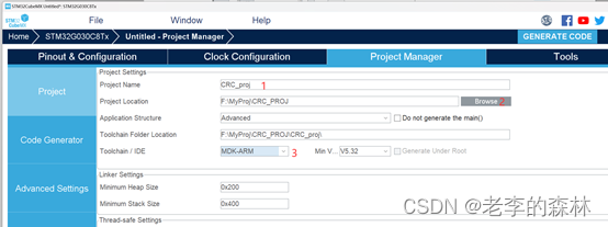
Enter the project name at 1.
Select the project path at 2.
Select the software to be developed in the future at 3. I use Keil so I choose MDK and
set it as shown in the Code Generator option
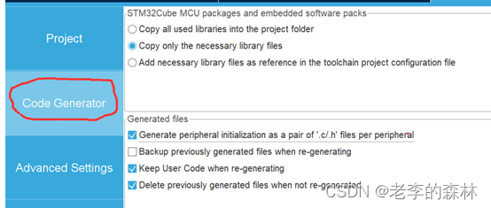
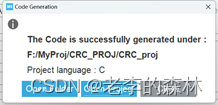
Finally, click GENERATE CODE in the upper right corner to generate the project,

When the following interface pops up, it means that the project has been generated. Click Open Project to open the project and start development.