Table of contents
Table of contents
Basics of Storage Technology
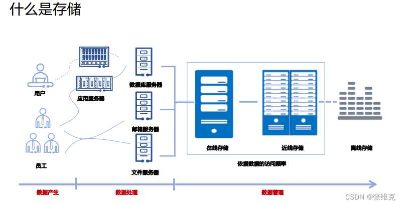
Narrow storage definition: CD, DVD, ZIP, tape, hard disk and other storage media
Generalized storage definition:
▫ Storage hardware system (disk array, controller, disk cabinet, tape library, etc.)
▫ Storage software (backup software, management software, snapshot, replication and other value-added software)
▫ Storage network (HBA card, fiber switch, FC/SAS cable, etc.)
▫ Storage solutions (centralized storage, archiving, backup, disaster recovery, etc.)
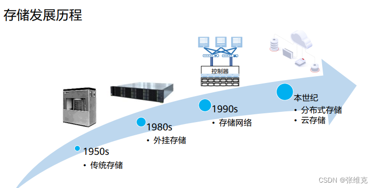
The development of storage architecture has gone through several stages: traditional storage, plug-in storage, storage network, distributed storage, and cloud storage.
SAN is a typical storage network, which mainly uses FC network to transmit data, and then IP storage area network appeared.
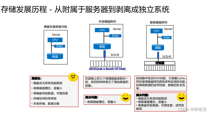
Plug-in storage refers to direct-attached storage. The earliest form is JBOD, which is just connecting some disks together. It is called JBOD (Just a Bunch Of Disks, disk cluster). What the host sees is a bunch of independent hard disks, only adding The capacity cannot be guaranteed.
• Distributed storage uses general-purpose server hardware to build a storage resource pool, which is more suitable for cloud computing scenarios.

Introduction to DAS storage
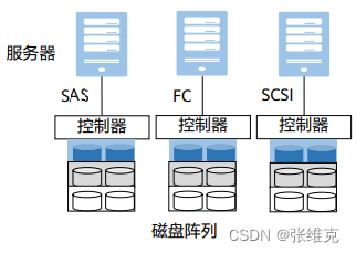
DAS(Direct Attached Storage)
Time: 70s
Background: Users first generated storage requirements due to the increase in data volume, resulting in the earliest and simplest storage architecture: direct-attached additional storage DAS
Connection mode: FC, SCSI, SAS
Access method: The connection channel between direct-attached storage and server host usually adopts SAS connection
Link rate: 3 Gbit/s, 6 Gbit/s, 12 Gbit/s
Provide snapshot, backup and other functions
Introduction to NAS storage (1)

NFS was developed to allow file sharing between systems on a local area network.
The Linux NFS client supports three versions of the NFS protocol: NFSv2 [RFC1094], NFSv3 [RFC1813], and NFSv4 [RFC3530]. Among them, NFSv2 uses the UDP protocol, which has limited data access and transmission capabilities and is outdated;
The working mechanism of NFS: mainly adopts the remote procedure call RPC mechanism.
▫ RPC provides a set of operations for accessing remote files that are independent of machines, operating systems, and low-level transfer protocols, allowing remote clients to access them over the network in a manner similar to the local file system.
▫ The NFS client initiates an RPC request to the NFS server, and the server passes the request to the local file access process, and then reads the local disk file on the server host and returns it to the client.
CIFS (Common Internet File System) is a network file system protocol used to provide shared access to files and printers between machines on a network. Now it mainly implements the network file sharing function between Windows hosts.
Introduction to NAS storage (2)
NAS: Network Attached Storage, network attached storage, is a technology that integrates distributed and independent data and centralizes management to facilitate access to different hosts and application servers.
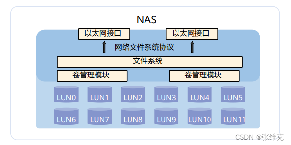
NAS can be used as a network node and directly connected to the network. In theory, NAS can support various network technologies and network topologies, but Ethernet is currently the most common network connection method. We mainly discuss the use of Ethernet as the Network-based NAS environment.
NAS itself can support multiple protocols (such as NFS, CIFS, etc.), and can support various operating systems. Through any workstation, the NAS device can be managed intuitively and conveniently by using IE or Netscape browser.
Introduction to SAN storage
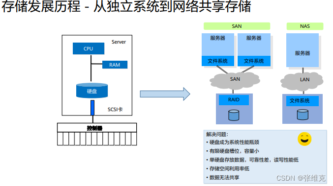
SAN: Storage Area Networks, storage area network, is a dedicated storage system that connects one or more network storage devices and servers through a dedicated high-speed network.
Storage Area Networks (SAN): A storage network is a dedicated, high-performance network architecture used between servers and storage resources. SAN is a dedicated network for server backend storage independent of LAN. SAN uses a scalable network topology to connect servers and storage devices. Each storage device does not belong to any server, and all storage devices can be shared as peer-to-peer resources among all network servers.
SAN mainly uses Fiber Channel Protocol (Fibre Channel Protocol) to establish a direct connection with servers and storage devices through FC switches, so we usually call this SAN established using FC connections as FC-SAN. FC is particularly suitable for this application because on the one hand it can transmit large data blocks and on the other hand it can transmit over longer distances. SAN is mainly used in high-end, enterprise-level storage applications that have high requirements for performance, redundancy, and data availability.
With the development of storage technology, IP-SAN based on TCP/IP protocol is also widely used. IP-SAN has good scalability, flexible interoperability, and can break through the limitation of transmission distance. It has obvious cost advantages and easy management and maintenance.
The biggest difference between NAS and SAN is that NAS has a file operation and management system, but SAN does not have such a system function, and its function only stays at the next layer of file management, that is, data management. SAN and NAS are not in conflict with each other, and can coexist in a system network, but NAS realizes space management and resource sharing through a common interface, and SAN only provides a dedicated fast rear storage channel for server storage data.
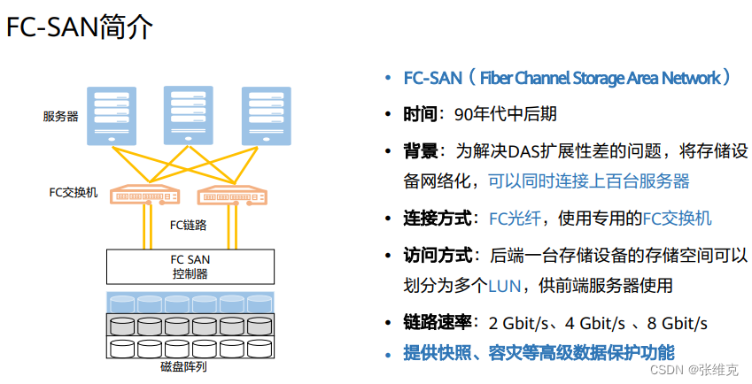
• FC: Fiber Channel, Fiber Channel, refers to a standard data storage network used to transmit 100 Mbit/s to 4.25 Gbit/s signals on optical fiber or copper cables. High-speed transmission technology used to build storage area networks. Fiber Channel can be used in general networks that support protocols such as ATM, IP, etc., but its main use is to transport Small Computer System Interface (SCSI) traffic from servers to disk arrays.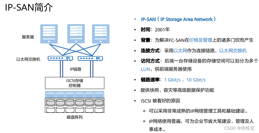
iSCSI: Internet Small Computer System Interface, Internet Small Computer System Interface, is a storage technology based on the Internet and the SCSI-3 protocol. The distance can be extended infinitely.
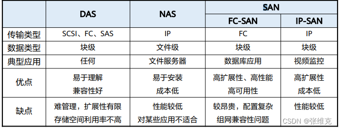
Summary and comparison of three storage networks
Introduction to Storage Form
centralized storage
Centralized storage system, that is, the entire storage is concentrated in one system. Enterprise-level storage devices are generally centralized storage. But centralized storage is not a single device, but multiple devices concentrated in a system. Taking Huawei's storage as an example, the entire storage system may require several cabinets for storage. Centralized storage can be divided into SAN and NAS according to the technical architecture, and SAN can be subdivided into FC-SAN and IP-SAN.
The biggest feature of centralized storage is that the deployment structure is simple, and there is no need to consider how to deploy services to multiple nodes, nor does it need to consider the distributed collaboration between multiple nodes.
Disadvantages of centralized storage:
▫ Isolated storage resources, the storage is connected to a limited number of servers through a dedicated network;
▫ Centralized vertical expansion is achieved by adding hard disk enclosures, and the hardware controller performance (single controller with disk capability) becomes the bottleneck;
▫ The horizontal expansion of centralized storage needs to be fully connected through the controller, and the performance of the hardware controller becomes the bottleneck of expansion;
▫ Centralized storage resources lack sharing. Storage devices and resources are often provided by different manufacturers, and resources cannot be shared between devices. What the data center sees are isolated storage pools;
▫ Centralized storage adopts a centralized metadata management method, the concurrent operation capability provided by the system will be limited by the performance of the metadata service, and the metadata service will also become the performance bottleneck of the system;
distributed storage
A distributed storage system stores data dispersedly on multiple independent servers. The distributed network storage system adopts a scalable system structure and uses multiple storage servers to share the storage load. It not only improves the reliability, availability and access efficiency of the system, but is also easy to expand. As distributed storage becomes more and more popular, some applications with higher performance requirements are now beginning to use distributed storage, such as databases in financial systems.
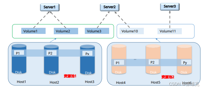
Distributed storage uses software to reconstruct the storage service form, while simulating the functions of the original hardware controller through software, while avoiding various disadvantages of the hardware controller.
Resource pool: Similar to the RAID group concept of SAN.
storage business type

Object storage is a new storage technology. The object storage system combines the advantages of NAS and SAN. It also has the advantages of high-speed direct access of SAN and data sharing of NAS. It provides high reliability, cross-platform and secure data sharing. storage architecture. The comparison between object storage, block storage and file storage is as follows:
▫ Block storage directly accesses the storage layer, with the least overhead, the highest efficiency, and the fastest speed. But the cost is the highest and expansion is difficult. Block storage adopts the iSCSI/FC protocol, which is difficult to transfer across the network. Suitable application scenarios are enterprise databases, such as running Oracle, etc.;
▫ File storage builds a file system on top of block storage, and organizes data in a directory-directory-file manner, which is easier to manage. Because most applications operate on files, file storage is easier to interface with application systems. The file system is limited by the directory tree, and its scalability is limited, generally extending to tens of PB at most. The file system is suitable for enterprise internal application integration and file sharing scenarios;
▫ Object storage builds an object management layer on top of block storage. Compared with the file system, the object system layer is flat and has fewer expansion restrictions, so it has almost unlimited scalability. Objects are composed of unique Key, files, data (files), metadata, and custom metadata. Because they contain self-management information, they are more intelligent. Object storage adopts a standard-compatible Internet protocol interface and can be transmitted across regions. Object storage is suitable for storage scenarios facing Internet services, as well as archiving and backup scenarios within enterprises.
storage key technology
RAID technology
storage protocol
Basic concepts of RAID
RAID: Redundant Array of Independent Disks, redundant array of independent disks, RAID technology combines multiple separate physical hard disks into a logical hard disk in different ways, thereby improving the read-write performance and data security of the hard disk.
According to different combinations, it can be divided into different RAID levels
Using two different RAID methods at the same time can also be combined into a new RAID level
RAID data organization form
Hard disk striping: Divide the hard disk space into multiple stripes according to the set size, and divide the data modules according to the size of the stripes when writing data.
Strip (strip): A single or multiple consecutive sectors in a hard disk form a strip, which is an element that makes up a strip.
Stripe: A stripe of the same "position" (or the same number) on multiple hard drives in the same hard disk array.
RAID data protection method
Method 1: Mirroring (Mirroring), save a copy of the data on another redundant hard disk.
Method 2: parity check algorithm (XOR).
XOR operation is widely used in digital electronics and computer science.
Algorithm of XOR check—false if same, true if different:
0⊕0=0; 0⊕1=1; 1⊕0=1; 1⊕1=0;
RAID technology usually has 2 different ways to protect data:
▫ Save a copy of data on another redundant hard disk to improve reliability and read performance.
▫ Use parity check algorithm. Parity is additional information calculated using user data. For RAID types that use parity, it means additional parity drives are required. The parity check uses the XOR (XOR calculation symbol ⊕) algorithm.
RAID Hot Standby and Reconfiguration Concepts
Definition of Hot Spare
When a hard disk in the redundant RAID group fails, without interfering with the normal use of the current RAID system, another normal spare hard disk in the RAID system will automatically replace the failed hard disk to ensure the redundancy of the RAID system in time.
Hot standby is generally divided into two types
Global: The spare hard disk is shared by all redundant RAID groups in the system.
Dedicated type: the spare hard disk is dedicated to a redundant RAID group in the system
Data verification, which uses redundant data to detect and repair data errors. Redundant data is usually calculated using algorithms such as Hamming codes and XOR operations.
Using the parity function can greatly improve the reliability, high performance and fault tolerance of the disk array.
However, data verification needs to read data from multiple places and perform calculations and comparisons, which will affect system performance.
Generally speaking, RAID cannot be used as a substitute for data backup, and it cannot do anything about data loss caused by non-disk failures, such as viruses, man-made destruction, accidental deletion, etc. The data loss at this time is relative to the operating system, file system, volume manager or application system. For RAID, the data is intact and no loss occurs. Therefore, data protection measures such as data backup and disaster recovery are very necessary, and complement each other with RAID to protect the security of data at different levels and prevent data loss.
Introduction to Common RAID Levels

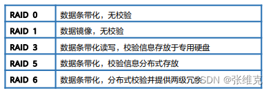
RAID 0: Striped hard disk array without fault-tolerant design, the data of the RAID group is evenly distributed among the hard disks in the form of stripes.
RAID 1: Also known as mirroring (Mirror), data is written to the primary hard disk and the mirroring hard disk at the same time.
RAID 3: A parallel data transmission array with parity, the data is striped and distributed in the data disk, and a dedicated parity hard disk is used to store the parity data.
RAID 5: Similar to the RAID 3 mechanism, but the verification data is evenly distributed on each data hard disk, the RAID member hard disks store data and verification information at the same time, and the data blocks and corresponding verification information are stored on different hard disks. RAID 5 is one of the most commonly used RAID methods.
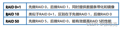
RAID 10: A RAID level that combines mirroring and stripes in two levels. The first level is a RAID 1 mirror pair, and the second level is a RAID 0. RAID 10 is also a widely used RAID level.
Working principle of RAID 6 DP
DP: Double Parity, that is, on the basis of the one row XOR parity hard disk used in RAID 4, another hard disk is added to store the oblique XOR parity information.
P0-P3 in the horizontal verification disk is the verification information of the horizontal data in each data disk.
例:P0=D0 XOR D1 XOR D2 XOR D3
The DP0-DP3 in the oblique verification disk are the oblique data verification information of each data disk and the horizontal verification disk.
Example:DP0=D0 XOR D5 XOR D10 XOR D15
RAID 6 DP also has two independent parity data blocks. The first verification information is the same as the first verification value of RAID 6 P+Q, and the second is different from RAID 6 P+Q, using oblique XOR operation to obtain row diagonal parity data piece. The row parity value is obtained by XOR operation of user data in the same stripe, as shown in the figure: P0 is obtained by XOR operation of D0, D1, D2 and D3 on stripe 0
The second parity data block is XORed by the diagonal data block of the array. The selection process of the data block is more complicated. DP0 is obtained by XOR operation of D0 on stripe 0 of hard disk 1, D5 on stripe 1 of hard disk 2, D10 of stripe 2 on hard disk 3, and D15 on stripe 3 of hard disk 4. DP1 is obtained by XORing D1 on stripe 0 of hard disk 2, D6 on stripe 1 of hard disk 3, D11 on stripe 2 of hard disk 4, and P3 on stripe 3 of the first verification hard disk. . DP2 is obtained by XOR operation of D2 on stripe 0 of hard disk 3, D7 of stripe 1 on hard disk 4, P2 of even-even hard disk stripe 2, and D12 on stripe 3 of hard disk 1. Therefore, DP0 = D0⊕D5⊕D10⊕D15, DP1 = D1⊕D6⊕D11⊕P3, and so on.
A RAID 6 array can tolerate the failure of two hard drives.
The performance of a RAID 6 group, regardless of whether the algorithm is DP or P+Q, is relatively slow. Therefore, RAID 6 is suitable for two scenarios:
▫ Data is critical and needs to be online and available for as long as possible.
▫ The capacity of the hard disk used is very large (usually more than 2 T). The reconstruction time of a large-capacity hard disk is longer, and if two hard disks fail, the data will be inaccessible for a long time. In RAID 6, one hard disk can be reconstructed when another hard disk fails. Some enterprises hope that after using large-capacity hard drives, the storage array supplier will use a double-protected RAID group.
Introduction to RAID 2.0 Technology
RAID 2.0
Enhanced RAID technology effectively solves the problem that the capacity of mechanical hard disks is increasing, and the time required to rebuild a mechanical hard disk is getting longer and longer. The traditional RAID group reconstruction window is getting larger and larger, resulting in a hard disk failure during the reconstruction period. The question of total data loss risk.
RAID 2.0+
On the basis of RAID 2.0, it provides more fine-grained (up to tens of KB granularity) resource granules to form a standard allocation and recovery unit of storage resources, similar to virtual machines in computing virtualization, which we call virtual block technology .
Huawei RAID 2.0+
It is a brand-new RAID technology designed by Huawei to meet the development trend of storage technology virtualization architecture in view of the shortcomings of traditional RAID. Its traditional fixed management mode is a two-layer virtualization management mode. ) on the basis of hard disk management, through a series of Smart efficiency improvement software, the efficient resource management of the upper layer virtualization (Virtual for Pool) is realized.
The meaning of block-level virtualization is to divide the hard disk in the system into several continuous fixed-size storage spaces, which are called storage blocks, namely Chunk, or CK for short.
RAID 2.0+ block virtualization technology
The stored data will eventually be stored on SSD disks. If the data stored on some disks is uneven, some SSD disks with high pressure may become the bottleneck of the system.
To deal with this problem, Huawei's storage system adopts the new RAID 2.0+ block virtualization technology. Through finer-grained division, the data of all LUNs is evenly distributed on each SSD disk to achieve disk load balancing.
1. Multiple hard disks form a storage pool.
2. The storage system divides each SSD in the storage pool into CKs of fixed size (usually 4MB) for logical space management.
3. CHUNKs from different SSD hard disks form CKG according to the "RAID strategy" set by the user on DeviceManager.
4. CKG is divided into finer grains (usually 8KB). When a user creates a LUN, the storage system maps it to the LUN in units of grains to implement fine-grained management of storage resources.
• Compared with the traditional RAID mechanism, RAID2.0+ has the following advantages:
• Service load balancing to avoid hot spots. The data is distributed to all hard disks in the resource pool. There are no hot spots, and the load on the hard disks is even. This prevents individual disks from reaching the upper limit of life in advance due to more write operations.
• Rapid refactoring to narrow the risk window. When a hard disk fails, the valid data on the failed disk will be reconstructed to all disks in the resource pool except the failed disk, realizing many-to-many reconstruction, which is fast and greatly shortens the time that data is in a non-redundant state.
• Full participation in refactoring. All hard disks in the resource pool will participate in reconstruction. The reconstruction load of each disk is very low, and the reconstruction process has no impact on upper-layer applications.