overview
The vector control of the permanent magnet synchronous motor (PMSM) can be described as an entry-level control. Simply put, it is to obtain the current required voltage of the stator through some means, and to generate the corresponding speed.
Vector control is a means to control the corresponding voltage output by the inverter. Its essence is to use Clark transformation and Park transformation to decouple the excitation component and torque component of the motor current, and decouple the three-phase stator current into idi_{d} (mainly controlling the excitation and also affecting the torque) and iqi_{q} (controlling the torque). , only by the fixed excitation of the rotor permanent magnets.
1. Three-phase PMSM coordinate transformation
The relationship between the coordinate systems is shown in Figure 1:

1.1 Clark transform
The coordinate transformation of the natural coordinate system ABC to the static coordinate system α−β\alpha-\beta is Clark transformation. According to the relationship between the coordinate systems shown in Figure 1, we can get:

Among them: f represents the voltage, current and other variables of the motor; T3s/2sT_{3s/2s} is the coordinate transformation matrix, which can be expressed as:

The coordinate transformation of the stationary coordinate system α−β\alpha-\beta to the natural coordinate system ABC is called the inverse Clark transformation, expressed as:

Where T2s/3sT_{2s/3s} is the coordinate transformation matrix, expressed as:

1.2 Park transformation
The coordinate transformation of the stationary coordinate system α−β\alpha-\beta to the synchronous rotating coordinate system d−qd-q is called Park transformation. According to the relationship between the coordinate systems shown in Figure 1, the following formula can be obtained:

Among them, T2s/2rT_{2s/2r} is the coordinate transformation matrix, which can be expressed as:

The coordinate transformation of the synchronous rotating coordinate system d−qd-q to the coordinate transformation of the stationary coordinate system α−β\alpha-\beta is an inverse Park transformation, which can be expressed as:

Among them, T2r/2sT_{2r/2s} is the coordinate transformation matrix, which can be expressed as:

According to the above transformation, the relationship between the natural coordinate system ABC and the synchronous rotating coordinate system d−qd-q can be obtained:

Among them, T3s/2rT_{3s/2r} is the coordinate transformation matrix, which can be expressed as:

The relationship between the synchronously rotating coordinate system d−qd-q transformation to the natural coordinate system ABC:

Among them, T2r/3sT_{2r/3s} is the coordinate transformation matrix, which can be expressed as:

2. PMSM Mathematical Modeling
The mathematical model under the synchronous rotating coordinate system d−qd-q, the stator voltage equation can be expressed as:

The stator flux equation is:

Substitute into the above formula to get:

At this time, the electromagnetic torque equation can be written as:

There are several important relations as follows:

Three, three-phase space vector
3.1 Introduction to three-phase space vector
The SVPWM control strategy uses the inverter space voltage vector switching to obtain a quasi-circular rotating magnetic field, so that the AC motor can obtain better control performance than the SPWM algorithm under the condition of low switching frequency. This method has a high degree of harmonic optimization, can increase voltage utilization, reduce motor torque ripple, is suitable for digital control systems, and is easy to control.
Space vector transformation, which converts the three scalars of the three-phase output of the inverter into a vector control, and its trajectory is shown in Figure 2:

According to Figure 2, 3 scalars are synthesized into a vector formula, and the vector synthesis is shown in Figure 3:

The voltage space vector UoutU_{out} is:

Discuss using the above methods to control a typical two-level three-phase voltage source inverter, first define sas_{a} , sbs_{b} , scs_{c} , when sas_{a} , sbs_{b} , scs_{c} are 1, it means that the upper bridge arm of the inverter is turned on and the lower bridge arm is turned off; otherwise, when sas_{a} , sbs_{b} , scs_{c} When it is 0, it means that the upper bridge arm of the inverter is turned off and the lower bridge arm is turned on. Because the upper and lower switches of the same bridge arm cannot be turned on at the same time, 8 basic voltage space vectors can be obtained, which are 000, 001, 010, 011, 100, 101, 110, 111, and the complex plane is divided into 6 regions, called sectors, as shown in Figure 4:

According to the two-level three-phase voltage source inverter in Figure 5, the formulas of each vector can be known as:


And, the relationship between the phase voltage UANU_{AN} , UBNU_{BN} , UCNU_{CN} and the switching function is:

3.2 Three-phase space vector synthesis (SVPWM)
Using switching functions to control two-level three-phase voltage source inverters can only obtain 8 vectors, but this is not enough to generate circular space vector motion trajectories. Therefore, the eight basic voltage space vectors are combined within a fixed switching period TsT_{s} by using the average value equivalent principle. Taking sectors as divisions, when the voltage space vector UoutU_{out} rotates to a certain sector, it can be obtained by combining two adjacent non-zero vectors and zero vectors at different times. Taking the first sector as an example, the space vector composite diagram is shown in Figure 6:

According to the balanced equivalence principle, we can get:


Among them, T4T_{4} and T6T_{6} are the action time of U4U_{4} and U6U_{6} respectively.
The action time T4T_{4} , T6T_{6} , T0T_{0} can be calculated through the geometric relationship in Figure 6, as follows:

Where θ\theta is the angle between the synthetic vector and the main vector. Substituting |U4|=|U6|=2/3∗Udc|U_{4}|=|U_{6}|=2/3*U_{dc} and |Uout|=Um|U_{out}|=U_{m} into the above formula, we can get:

4. Realization of SVPWM algorithm
As shown in Figure 7, it is the simulation model of the built SVPWM module:

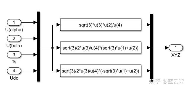
4.1 Voltage space vector sector judgment
In order to implement the SVPWM algorithm, the first thing to determine is which sector the voltage space vector is in, and based on this, determine the basic voltage vector used in the synthetic vector. Use uαu_{\alpha} , uβu_{\beta} to denote the components of the reference voltage vector UoutU_{out} on the α\alpha and β\beta axes, define three variables Uref1U_{ref1} , Uref2U_{ref2} , Uref3U_{ref3} , let:


Let N=4C+2B+A, the relationship with sectors can be obtained as shown in Table 1 below:

The sector simulation model built according to the above method is shown in Figure 8:

4.2 Calculation of the action time of each vector
It can be seen from Figure 6 that:

In the above formula, T4T_{4} and T6T_{6} are the action time of the adjacent vectors of each sector. When the voltage space vector is in different sectors, the corresponding adjacent vectors are different. Through the above formula, the absolute value of the action time of the corresponding adjacent vector when UoutU_{out} is in any sector can be expressed by the following three formulas:

The action time of each vector can be obtained as shown in Table 2:

For example, T4+T6>TsT_{4}+T_{6}>T_{s}, modulation processing is required, so:

As shown in Figure 9 and Figure 10, the simulation model of the action time of each vector in the sector and the action time of adjacent vectors in the sector:

4.3 Determination of sector vector switching point
First define:

The relationship between the three-phase voltage switching time switching points Tcm1T_{cm1}, Tcm2T_{cm2}, Tcm3T_{cm3} and each sector is shown in Table 3:

As for the specific principle, please refer to my previous answer:
The switching time calculation and PWM generation simulation model are shown in Figure 10:

5. PMSM vector control simulation based on PI regulator
5.1 Motor parameters
The simulink motor model has its own parameter model 11, and its specific parameters are shown in Table 4:

5.2 Simulation model and results
The simulation model built is shown in Figure 11:

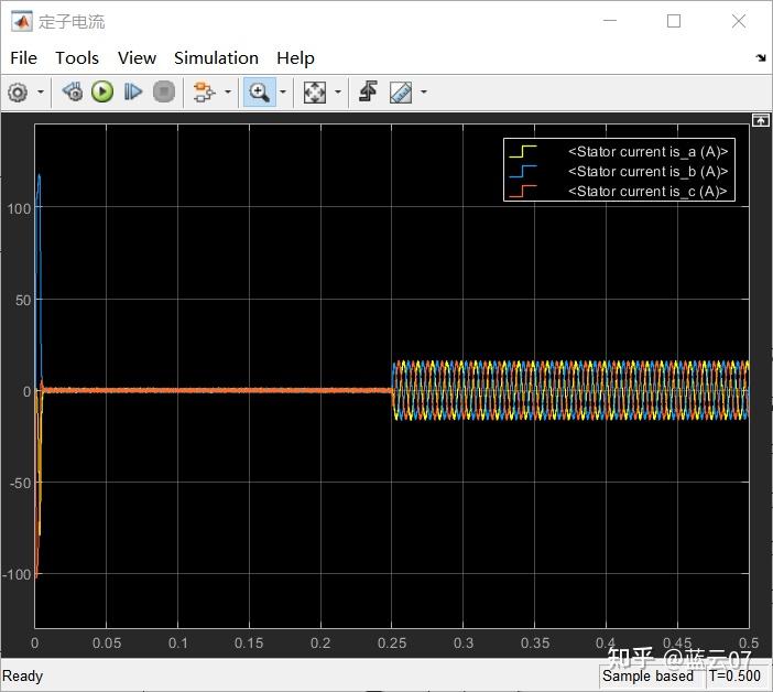
The load torque is set to 0 N⋅\cdotm, and becomes 10N⋅\cdotm at 0.25s, and the initial value of the given speed is n=1500r/min. The PI parameters of the speed loop are, Kp=0.45K_{p}=0.45, Ki=10K_{i}=10, and the output limit is [-120 120]. The PI parameters of the current loop are, Kp=21.3K_{p}=21.3, Ki=2.88e−6K_{i}=2.88e-6, and the limit is [-150 150].
The speed waveform is:

The torque waveform is:

Three-phase stator current waveform: