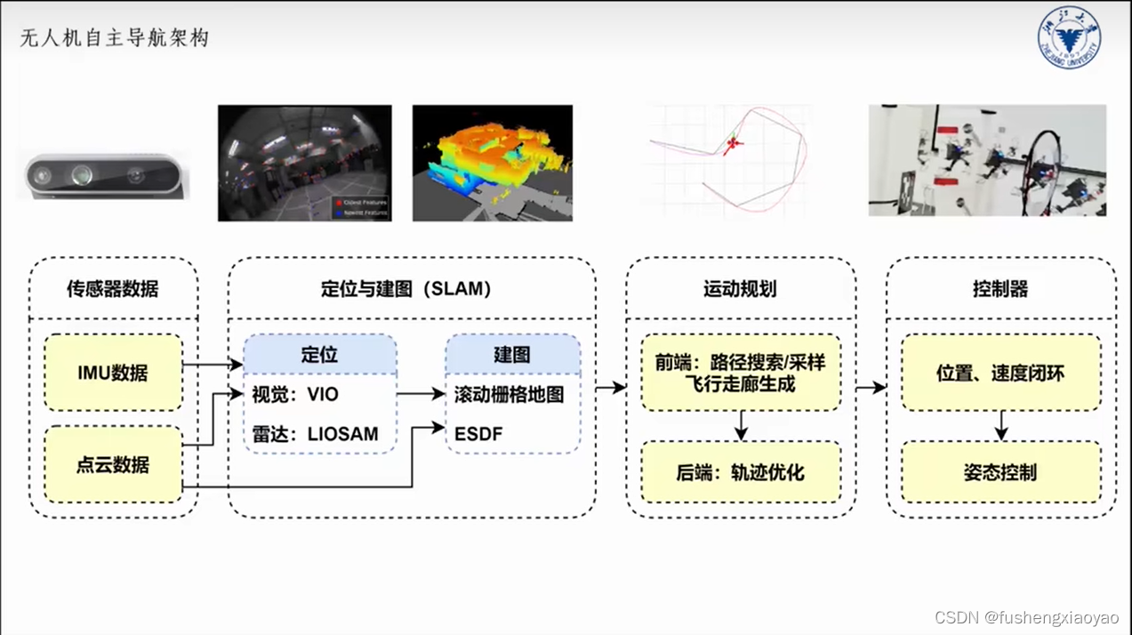
0. Complete block diagram

1. UAV software block diagram

The picture above is an overview of the PX4 firmware framework, and the blue squares refer to the various modules in the flight control system.
The functions of each module are introduced as follows:
- The Mavlink module is the most commonly used, and can be adjusted to off_board mode to cooperate with the onboard computer. The onboard computer can package the control information and the attitude information of the flight controller into MAVLink messages and send them to the flight controller.
- For the position control and attitude control modules in the figure, focus on the Offboard mode control interface
- For the position estimation and attitude estimation modules in the figure, the main focus is on the external measurement value interface
- The mixer module is mainly responsible for calculating the throttle value that reaches the expected torque and expected thrust, and sending it to the motor control module
2. UAV hardware model
The quadrotor UAV model is an important part of the position control and attitude control modules in the UAV firmware. For the specific structure and formula of the model, it is not necessary to remember the derivation process, but only need to remember what the input and output of each model are.
For the derivation of the dynamics model of the quadrotor UAV, please refer to the video of Station B: Design and Control of Multi-rotor Aircraft [Beihang-Quanquan-China MOCC] P29 Multi-rotor Control Model.
The quadrotor UAV model is mainly about how the position and attitude of the UAV will change after deriving a throttle amount for the UAV. Establishing a good UAV model is the premise to ensure the stable flight of UAV. The UAV model has a fixed derivation formula, but the parameters of the model need to be determined through a series of measurements, such as the UAV's mass, moment of inertia, and static parameters of the motor.
Quadrotor UAV models can be divided into:
Power system model (battery, ESC, motor and propeller, input: throttle, output: speed)
control efficiency model (depends on configuration, common configuration is quadrotor, input: speed, output: force and torque)
rigid body dynamics Model (force situation, input: force and torque, output: velocity and angular velocity)
rigid body kinematics model (state quantity relationship, input: velocity and angular velocity, output: position and attitude)
The relationship between each model is shown in the figure below
3. UAV closed-loop control
The closed-loop control of the quadrotor UAV is mainly to calculate the current throttle amount according to the current position and the expected position. The most common type of position controller and attitude controller is the cascade PID controller.
The closed-loop control control framework can be divided into:
Position control (input: desired position, output: desired attitude and desired lift)
attitude control (input: desired attitude, output: desired torque)
control distribution (input: desired lift, torque, output: desired speed)
motor control (input: desired rpm, output: desired throttle)
The closed-loop control framework of the quadrotor UAV is shown in the figure below:

