1. The difference between GPIO and I/O (see " Part13-How to distinguish I/O and GPIO " for details)
1. I/O
IO is Input Output, which is the input and output system in the computer, and is used for information exchange between the CPU and the outside world. For example, the CPU needs an I/O system to read memory data, and the I/O system is also required to output data from the CPU to the screen. Information can be transmitted in parallel or in parallel on the I/O system. That is, data is transmitted on multiple lines, that is, multiple bits are transmitted in parallel at a time, and one bit is transmitted serially at a time.
2. GPIO
GPIO, the full English name is General-Purpose IO ports, that is, general-purpose I/O ports. A "general-purpose programmable I/O interface" is generally provided on the microcontroller chip. The interface has at least two registers, namely "control direction register" and "data register". Each bit of the data register is directly connected to the outside of the chip, and the function of each bit in the data register, that is, whether the signal flow direction of each bit is input or output, can be set independently through the corresponding bit in the control register. In this way, the presence or absence of an IO interface becomes a feature that distinguishes microcontrollers from microprocessors. (Different MCUs have different register configurations)
2. GPIO of K210
K210 uses FPIOA (Field Programmable IO Array), so each time you use the hardware IO port, you need to perform pin mapping on the hardware IO port. Moreover, what is called in the software is also software-mapped software GPIO, which allows users to map 255 internal functions to 48 free IOs on the periphery of the chip: • Supports
IO programmable function selection
• Supports 8 kinds of drive capability options for IO output
• Support IO internal pull-up resistor selection
• Support IO internal pull-down resistor selection
• Support IO input internal Schmitt trigger setting
• Support IO output slope control
• Support internal input logic level setting
The following GPIOHS on MAIX BIT have been used by default, and try not to use them unless necessary in the program:
| GPIOHS | Function |
|---|---|
| GPIOHS31 | LCD_DC |
| GPIOHS30 | LCD_RST |
| GPIOHS29 | SD_CS |
| GPIOHS28 | MIC_LED_CLK |
| GPIOHS27 | MIC_LED_DATA |
More can be viewed in the schematic diagram of MAIX BIT
Three, GPIO function
1、
class GPIO(ID, MODE, PULL, VALUE)
Create a new SPI object with specified parameters
Parameter description:
ID: GPIO pin used (be sure to use the constants in GPIO to specify, such as GPIO0, GPIO1)
MODE: GPIO mode
• GPIO.IN is input mode
• GPIO.OUT is output mode
PULL: GPIO pull-up and pull-down mode
• GPIO.PULL_UP pull up
• GPIO.PULL_DOWN pull down
• GPIO.PULL_NONE neither pull up nor pull down
2、
GPIO.value([value])
Modify/read GPIO pin status
Parameter description:
[value]: optional parameter, if this parameter is not empty, return the current GPIO pin status
3、
GPIO.irq(CALLBACK_FUNC,TRIGGER_CONDITION,GPIO.WAKEUP_NOT_SUPPORT,PRORITY)
Configure an interrupt handler to be called when the pin's trigger source is active. If the pin mode is pin.in, the trigger source is the external value on the pin.
Parameter description:
CALLBACK_FUNC: Interrupt callback function, which is called when an interrupt is triggered, an entry function pin_num
• PIN_NUM returns the GPIO pin number that triggered the interrupt (only GPIOHS supports interrupts, so the pin number here is also the pin number of GPIOHS)
TRIGGER_CONDITION: Interrupt trigger mode for GPIO pins
• GPIO.IRQ_RISING rising edge trigger
• GPIO.IRQ_FALLING falling edge trigger
• GPIO.IRQ_BOTH triggers on both rising and falling edges
4、
GPIO.disirq()
Disable interrupt
5、
GPIO.mode(MODE)
Set GPIO input and output mode
Parameter description:
MODE:
• GPIO.IN input mode
• GPIO.PULL_UP pull-up input mode
• GPIO.PULL_DOWN pull-down input mode
• GPIO.OUT output mode
4. FPIOAs
K210 supports free mapping of each peripheral to any pin, using the FPIOA function to achieve, click here to view peripheral table
1, help(func)
displays peripherals and their brief descriptions
from Maix import FPIOA

fpioa = FPIOA()
fpioa.help()
fpioa.help(0)
fpioa.help(fpioa.JTAG_TCLK)
Parameter description:
func: Peripheral name (function/number), you can not pass parameters, and all peripheral names will be displayed in the form of a table, which is a brief description. This table can also be found at the end of this page (Appendix: Peripheral table) ; If passing parameters, pass an integer value, and print the peripheral name and description after finding the peripheral corresponding to the number, such as FPIOA.JTAG_TCLK or fm.fpioa.JTAG_TCLK (fm is introduced later in this page) or 0
2. set_function(pin, func)
sets the peripheral function corresponding to the pin, that is, pin mapping
fpioa = FPIOA()
fpioa.set_function(board_info.LED_G, fm.fpioa.GPIOHS0)
Parameter description:
pin: pin number, value [0, 47], please refer to the circuit diagram for the specific pin connection, or use board_info. Then press the TAB button to complete to get the common pins of the board, such as board_info.LED_G
func : Peripheral function, pass an integer value, you can use fm.fpioa.help() or check the peripheral table.
For example, you need to map the pin connected to the green LED to high-speed GPIO0:
3. get_Pin_num(func)
obtains which pin the peripheral is mapped to
5. Turn on the LED
Now that you understand the GPIO and FPIOA functions of MAIX BIT, the next step is to light up the LED, just like the first step in learning all microcontrollers.
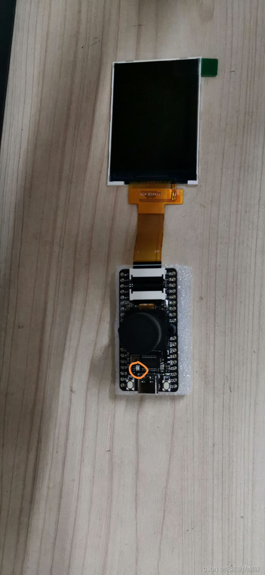
By observing the MAIX BIT, we can see that it has an RGB light on board (looking for a long time)
and then look at the schematic diagram to know that rgb is connected to the three pins io12, io13, and io14 respectively, and is used to light up


MaixPy at a low level. The pins (hardware pins) corresponding to the on-chip peripherals of the used hardware K210 can be mapped arbitrarily, compared with the K210 hardware design and software design, the degree of freedom is greater. For example, I2C can use Pin11 and Pin12, and can also be changed to any other pins. Because of this powerful mapping function, when using pins, it is necessary to add a step of mapping:
from fpioa_manager import fm    # 导入库
fm.register(12, fm.fpioa.GPIO0)
Here we map pin 14 to the function of GPIO0. After executing this command, pin 14 and GPIO0 are mapped (bound). To unmap (unbind), you need to call the fm.unregister function.
Light up the LED code
from fpioa_manager import fm
from Maix import GPIO

io_led_blue = 14
fm.register(io_led_blue, fm.fpioa.GPIO0)

led_b=GPIO(GPIO.GPIO0, GPIO.OUT)
led_b.value(0)
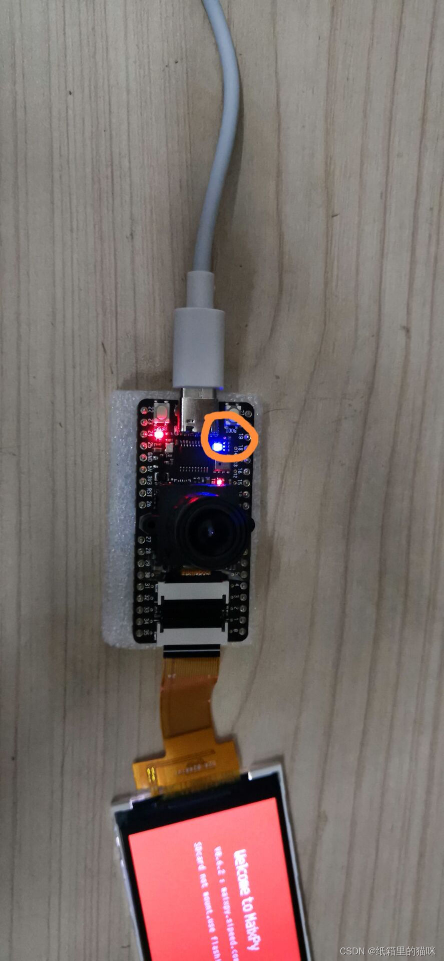
After running the code online, we found that the blue light was lit.
Analyze the code:
import the fm object from the fpioa_manager package, which is mainly used for mapping pins and peripherals
The GPIO class is imported from the package Maix, GPIO peripheral related operations
Define a variable io_led_blue with a value of 14, that is, Pin13/IO13, which pin of the chip is connected to the specific LED pin, please see the schematic diagram in the previous development board introduction
Use the built-in object fm (abbreviation of fpioa manager) to register the corresponding relationship between the chip's peripherals and pins, where fm.fpioa.GPIO0 is a GPIO peripheral of K210 (note the distinction between GPIO (peripherals) and pins ( The real hardware pin) difference), so register fm.fpioa.GPIO0 to pin IO14;
Use led_b.value(1) or led_b.value(0) to set the high and low level, because the low level is set here, according to the above schematic diagram, the low level is turned on and the LED is on
Summarize
The pins (hardware pins) corresponding to the on-chip peripherals of the K210 can be mapped arbitrarily. In contrast, the K210 has a greater degree of freedom in hardware design and software design.