Table of contents
1.1 Analysis of Functional Requirements
1.2 Analysis of Technical Requirements
1.3 Network Security Requirements Analysis
2.2 IP planning and VLAN division
2.3 Core Layer Device Configuration
2.3.3 ACL access control configuration
2.4 Convergence Layer Device Configuration
2.4.2 ospf and overhead modification configuration
2.4.4 DHCP address pool configuration
2.4.5 mstp spanning tree configuration
2.5 Access layer configuration
2.6 Firewall and NAT configuration
2.7 Campus network server configuration
3.1 Equipment selection principles
3.2 Selection of core layer switches
1. Network demand analysis
1.1 Analysis of Functional Requirements
- The campus network is connected to the Internet, and teachers and students can obtain resources and information through the Internet.
- Realize file transfer and sharing within the campus network.
- Realize the paperless office of school teachers and administration.
1.2 Analysis of Technical Requirements
- IP planning: The campus network is characterized by a large number of terminals. Different network areas are divided according to different functions, and IP planning must be appropriate.
- Server: The servers in the campus network need to be turned on 24 hours a day, so a dedicated server room site is required, and professional operation and maintenance personnel are required to take care of it.
- The network needs to have high redundancy to avoid a single point of failure.
- The choice of ISP access to the campus network should be appropriate, and a certain number of IPs and multiple link bandwidths should be purchased according to the number of students in the school and campus services.
- Due to the large traffic in the campus network, corresponding VLANs need to be divided to divide broadcast domains and save network bandwidth. And achieve traffic load balancing.
1.3 Network Security Requirements Analysis
- Because the campus network is connected to the Internet, firewall devices are required to protect the data security of intranet users, filter bad information, and control the permissions of Internet users.
- All intranet users are prohibited from pinging the server.
- All intranet users are not allowed to access the Finance Department, and the Finance Department is not allowed to access the Internet.
- Intranet users are allowed to access the server.
- Extranet users cannot directly access intranet users, and intranet users can access the extranet except the finance department.
2. Campus LAN design
2.1 Topology diagram
According to the demand analysis, design the topology diagram of the campus network built this time, as shown in the following figure:
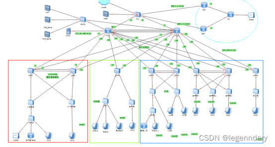
The campus network network is divided into three layers as a whole: the core layer, the aggregation layer and the access layer.
In order to realize redundant backup in the campus network and high-speed interconnection in the local area network, the core layer consists of two core nodes, including server clusters.
For buildings with large traffic, each building has two aggregation nodes. For ordinary classrooms with little network demand, the aggregation nodes can be shared to reduce cost investment. The aggregation layer is a three-layer switch. According to the needs of each building Different, one or two aggregation layer switches are used for aggregation respectively.
The access layer is a large number of access switches in each building, which are devices directly connected to users.
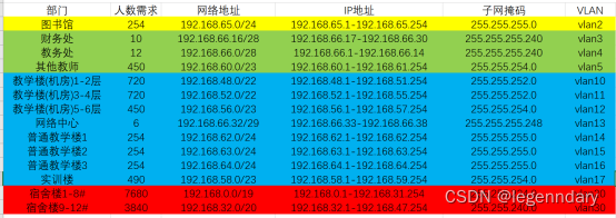
2.2 IP planning and VLAN division

2.3 Core Layer Device Configuration
2.3.1 IP address configuration
Core router node 1 configuration:
interface GigabitEthernet0/0/0
ip address 192.168.70.2 255.255.255.252
#
interface GigabitEthernet0/0/1
ip address 192.168.70.10 255.255.255.252
#
interface GigabitEthernet0/0/2
ip address 192.168.70.18 255.255.255.252
Configure port aggregation LACP:
interface Eth-Trunk0
undo portswitch
ip address 192.168.70.65 255.255.255.252
mode lacp-static #static lacp
max active-linknumber 2 ##Activate two links at most
Server cluster aggregation switch configuration:
interface Vlanif99
ip address 192.168.68.6 255.255.255.248
#
interface Vlanif117
ip address 192.168.70.69 255.255.255.252
2.3.2 ospf configuration
Core router node 1 configuration:
ospf 1 router-id 1.1.1.1
bfd all-interfaces enable //bfd links ospf to detect link status to speed up link convergence
area 0.0.0.0 //area 0
network 1.1.1.1 0.0.0.0
network 192.168.70.64 0.0.0.3
network 192.168.70.68 0.0.0.3
network 192.168.80.0 0.0.0.3
area 0.0.0.1 //area 1
network 192.168.70.0 0.0.0.3
network 192.168.70.8 0.0.0.3
area 0.0.0.2 //area 2
network 192.168.70.16 0.0.0.3
area 0.0.0.3 //area 3
network 192.168.70.24 0.0.0.3
network 192.168.70.32 0.0.0.3
network 192.168.70.40 0.0.0.3
network 192.168.70.48 0.0.0.3
network 192.168.70.56 0.0.0.3
network 192.168.70.72 0.0.0.3
2.3.3 ACL access control configuration
Core router node 1 configuration:
interface GigabitEthernet0/0/2
ip address 192.168.70.18 255.255.255.252
traffic-filter outbound acl 3000 //Place it in the outbound direction of the interface
acl number 3000
rule 5 deny icmp destination 192.168.66.16 0.0.0.15 icmp-type echo //All addresses are not allowed to initiate connections to the network segment of the Finance Department
Server cluster aggregation device configuration:
acl number 3000
rule 5 deny icmp destination 192.168.68.0 0.0.0.7 //The server of other devices is not allowed to initiate a ping operation
interface GigabitEthernet0/0/5
port link-type access
port default vlan 118
traffic-filter inbound acl 3000
2.4 Convergence Layer Device Configuration
2.4.1 Vlan and ip configuration
Dormitory aggregation node 1 configuration:
port trunk allow-pass vlan 2 to 4094
#
interface GigabitEthernet0/0/4
port link-type access
port default vlan 101
#
interface GigabitEthernet0/0/5
port link-type access
port default vlan 102
2.4.2 ospf and overhead modification configuration
BFD bidirectional forwarding detection is enabled on the entire network ospf. After detecting a fault in the link state, it is sent to the corresponding upper-layer application module for fast processing to speed up the convergence speed of the entire network. Modify the overhead of the ospf link to control the flow direction.
Dormitory aggregation node 1 configuration:
ospf 1 router-id 3.3.3.3
bfd all-interfaces enable
area 0.0.0.1
network 192.168.0.0 0.0.31.255
network 192.168.70.0 0.0.0.3
network 192.168.70.4 0.0.0.3
network 192.168.32.0 0.0.15.255
network 192.168.67.0 0.0.0.7
network 192.168.67.8 0.0.0.7
network 3.3.3.3 0.0.0.0
interface Vlanif20
ip address 192.168.0.1 255.255.224.0
ospf cost 5
interface Vlanif101
ip address 192.168.70.1 255.255.255.252
ospf cost 1 //Modify the cost to make the traffic of dormitory 1-8 go to core node A
#
interface Vlanif102
ip address 192.168.70.5 255.255.255.252
ospf cost 4
2.4.3 vrrp configuration
Dormitory aggregation node 1 configuration:
interface Vlanif20 //vlan of dormitory 1-8
ip address 192.168.0.1 255.255.224.0
vrrp vrid 1 virtual-ip 192.168.31.254 //virtual ip
vrrp vrid 1 priority 120 //Priority 120, default 100, set as vrrp master
vrrp vrid 1 track interface GigabitEthernet0/0/4 reduced 15 //Detect the upper layer direct link
vrrp vrid 1 track interface Eth-Trunk0 reduced 30
vrrp vrid 1 track interface GigabitEthernet0/0/5 reduced 15
vrrp vrid 1 track bfd-session session-name 1 reduced 30 //Use bfd to detect the upper link of the core layer to avoid suboptimal paths.
ospf cost 5
dhcp select global
#
interface Vlanif30 //dormitory 9-12 vlan
ip address 192.168.32.2 255.255.240.0
vrrp vrid 2 virtual-ip 192.168.47.254 //virtual ip
ospf cost 5
dhcp select global
#
interface Vlanif40 // AP device vlan of No. 1-8 dormitory
ip address 192.168.67.1 255.255.255.248
vrrp vrid 3 virtual-ip 192.168.67.6 //virtual ip
vrrp vrid 3 priority 120 //Priority 120 is set to master
vrrp vrid 3 track interface GigabitEthernet0/0/4 reduced 15
vrrp vrid 3 track interface Eth-Trunk0 reduced 30
vrrp vrid 3 track interface GigabitEthernet0/0/5 reduced 15
ospf cost 5
dhcp select global
#
interface Vlanif50 // AP equipment vlan of No. 9-12 dormitory
ip address 192.168.67.10 255.255.255.248
vrrp vrid 4 virtual-ip 192.168.67.14
ospf cost 5
dhcp select global
2.4.4 DHCP address pool configuration
Dormitory aggregation node 1 configuration:
ip pool vlan20
gateway-list 192.168.31.254
network 192.168.0.0 mask 255.255.224.0
dns-list 192.168.68.3
#
ip pool vlan30
gateway-list 192.168.47.254
network 192.168.32.0 mask 255.255.240.0
dns-list 192.168.68.3
#
ip pool vlan40
gateway-list 192.168.67.6
network 192.168.67.0 mask 255.255.255.248
excluded-ip-address 192.168.67.1 192.168.67.2
option 43 sub-option 2 ip-address 192.168.66.42
#
ip pool vlan50
gateway-list 192.168.67.14
network 192.168.67.8 mask 255.255.255.248
excluded-ip-address 192.168.67.9 192.168.67.10
option 43 sub-option 2 ip-address 192.168.66.42
2.4.5 mstp spanning tree configuration
Use MSTP multi-instance spanning tree protocol multi-instance one tree to divide different VLANs into instances to achieve load balancing and avoid causing devices to be idle.
Dormitory aggregation node 1 configuration:
stp instance 1 root primary
stp instance 2 root secondary
stp region-configuration
region-name lzc
revision-level 1
instance 1 vlan 20 40
instance 2 vlan 30 50
active region-configuration
2.5 Access layer configuration
2.5.1 Interface configuration
Dormitory access 1 configuration:
interface Ethernet0/0/1
port link-type trunk
port trunk allow-pass vlan 2 to 4094
#
interface Ethernet0/0/3
port link-type trunk
port trunk pvid vlan 40
port trunk allow-pass vlan 2 to 4094
#
interface Ethernet0/0/4
port link-type access
port default vlan 20
2.6 Firewall and NAT configuration
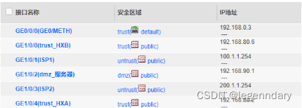
Firewall interface mode and IP address configuration, add the corresponding interface to the corresponding security zone and set an alias for easy management:
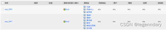
Configure NAT policy and security policy, and configure the security policy of the firewall according to requirements: allow access to the Internet except for the financial department, and set special time periods for dormitories, libraries, and computer rooms to allow access to the Internet.
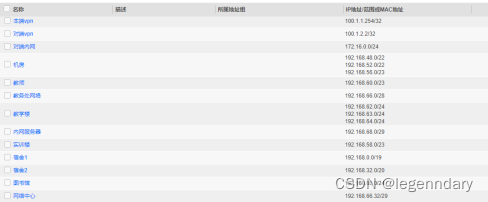
According to the IP address planning, create a reasonable ip address object for invocation and management during firewall configuration:
Add the Internet access time period for nat policy invocation:

Library access Internet security policy configuration:

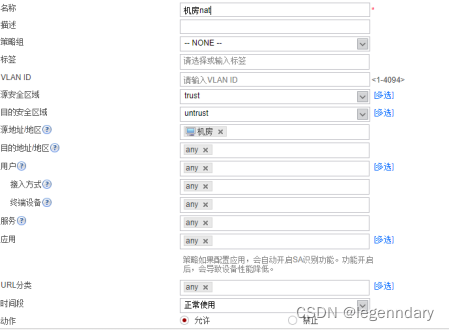
Computer room access Internet security policy configuration:
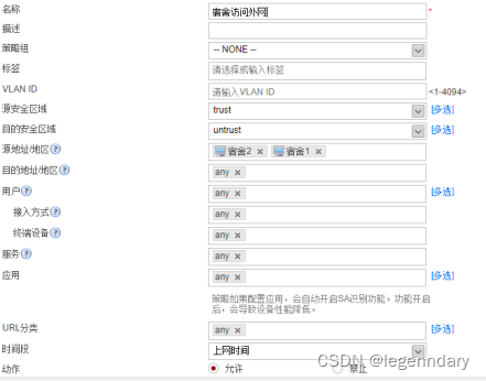
Internet security policy configuration for dormitory access:
Prohibit the Finance Department from accessing the Internet security policy configuration:

ISP1 NAT policy configuration:

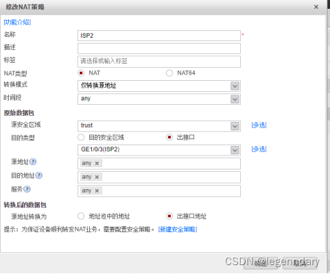
ISP2 NAT policy configuration:
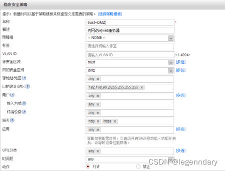
Allow extranet users to access the http server of the campus, and configure the security policy of the nat server:

Configure nat server:

Inter-zone security policy configuration:
Allow spontaneous traffic from the local area of the firewall to the trust area:

Use different isp links to access the Internet according to different traffic:
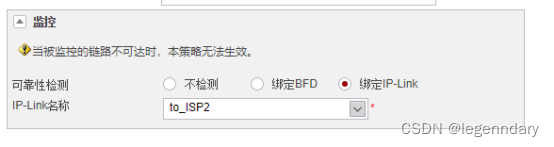
Bind ip link link detection on the routing policy:
2.7 Campus network server configuration
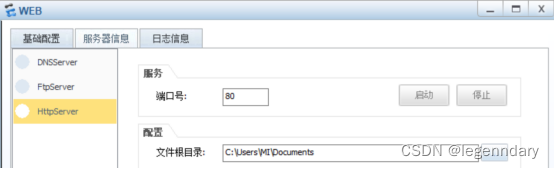
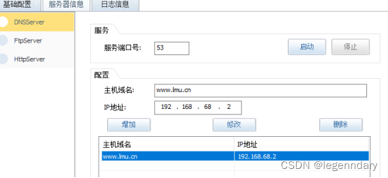
There are several types of servers mainly used: file server (ftp), website server (web), domain name server (DNS server), etc.
Select the root directory of the file to simulate the web server: use port 80
Simulation configuration FTP server settings file root directory, port number 21

Set the domain name to www.school.net and map the ip to the address of the web server:
Multicast source configuration:

Multicast router configuration:
[HX_A]multicast routing-enable
[HX_A]int g4/0/3
[HX_A-GigabitEthernet4/0/3]pim sm
[HX_A-GigabitEthernet4/0/3]int g2/0/2
[HX_A-GigabitEthernet2/0/2]pim sm
[HX_A-GigabitEthernet2/0/2]int g2/0/3
[HX_A-GigabitEthernet2/0/3]pim sm
[jxl_HJA-Vlanif111]int vlan 112
[jxl_HJA-Vlanif112]pim sm
[jxl_HJA-Vlanif111]pim sm
[jxl_HJA-Vlanif14]igmp enable
[jxl_HJA-Vlanif14]int vlan 15
[jxl_HJA-Vlanif15]
[jxl_HJA-Vlanif15]pim
[jxl_HJA-Vlanif15]pim sm
[jxl_HJA-Vlanif15]
[jxl_HJA-Vlanif15]ig
[jxl_HJA-Vlanif15]igmp en
[jxl_HJA-Vlanif15]igmp enable
3 Equipment selection
3.1 Equipment selection principles
We choose an appropriate brand and model for each device to meet the needs of the school. So when choosing equipment, we have to consider many issues. The first priority is to meet the needs of the school, and the cost performance must also be considered. In the case of the same price, choose a device with stronger performance. In the case of the same performance, we have to choose equipment with lower cost. In order to ensure the stability of the network, you must not choose equipment that has long been eliminated by the times. Although they are cheap, they can no longer carry the latest technology. You can't choose too novel equipment, these equipment are not mature enough and need to be improved. It is necessary to choose equipment with stable performance, high maturity, and continuous expansion.
3.2 Selection of core layer switches
Core layer switches should mainly consider switching capability and reliability, so products with no single point of failure in design should be selected. The high reliability of Huawei S9312 series switches has reached the level of operators. Some of the most important basic elements of this series of products, such as the main controller and power, are designed with redundancy, and all components support hot plugging. Dial, security and reliability meet the requirements. Therefore, service interruption can be reduced, non-destructive business upgrades can be performed, and comprehensive operation and maintenance detection and performance management can be supported. When network congestion occurs, data transmission delay, system jitter and other parameters can be counted, and network traffic can be monitored in real time and faults can be detected. Rapid positioning. Among them, the S9312 switch adopts a modular design. It supports 6 service slots, a backplane bandwidth of 12Tbps, a packet forwarding rate of 1344pps, and a single device supports 240 10G ports. Compared with the other two switches, it has more Excellent backplane bandwidth, relatively excellent packet conversion rate and modular ports, so Huawei S9303 was finally selected as the core layer switch, which provided the possibility for the core layer of the school enterprise network to upgrade to 10G switching capability. In addition, the S9312 switch supports the AC portal server function and the Access Point mode. It can automatically select the transmission channel and power when going online, and can automatically adjust the channel or power when information conflicts. Wireless devices switch quickly when roaming across access points, and wireless ACs can perform cold backup and load balancing in 1-to-1 and 1-to-many to improve reliability.
3.3 Access Layer Switches
What needs to be considered for the access layer switch is whether there are enough ports to allow all terminal devices to be connected to the network, can provide rich interfaces, and the adaptability of the switch at this layer should be strong enough to ensure that the information transmission process Stable operation, rich interfaces can be provided to ensure cost performance. Combining the requirements of the above-mentioned access layer switches, and comparing the parameters of various brands of switches, we found that Huawei S1730S-S24T4S switches have the highest backplane bandwidth, better packet conversion rate and more suitable number of ports, and the price is reasonable. Based on the comprehensive consideration of the above factors, the Huawei S1730S-S24T4S switch is more suitable.
3.4 Firewall selection
Huawei USG6500 series cloud management firewall is a firewall product supporting Huawei cloud management solution. It supports the "dual stack" mode of traditional firewall management and cloud management, and is suitable for providing cloud-based management security for small and medium-sized enterprises, large enterprise branches, chain institutions, etc. Internet service. Mobility, big data, and ICT integration have resulted in larger and larger enterprise networks, more and more complex networking, and higher and higher costs for network management and maintenance. In this context, Huawei has launched a cloud management network solution, which is supported by SDN technology, including cloud management platform and a full range of cloud network equipment, with cloud network management, network equipment plug and play, service configuration Advantages such as automation, O&M automation visualization, and network big data analysis can significantly solve the problems faced by traditional networks. The cloud management platform is operated by Huawei's enterprise public cloud, or built and operated by MSPs and operators themselves. Tenants only need to pay for firewall hardware and cloud management license fees to use various services provided by the cloud management platform. Network construction and maintenance are performed by Provided by the operator of the cloud management platform, it greatly saves the capital and manpower investment of the enterprise.
This design uses Huawei USG6530 firewall, which is characterized by plug and play, which simplifies network creation and deployment. After the device is started, it can be used by initiating authentication and registration to the cloud management platform. At the same time, the cloud management network solution introduces GLS, which can display the distribution of equipment in different regions. If a failure occurs, the location of the faulty equipment can be captured in time.
4 Network Test
↓↓↓↓↓↓↓↓↓↓↓↓↓↓↓↓↓↓↓↓↓↓↓↓↓↓↓↓↓↓↓↓↓↓↓↓↓↓↓↓↓↓↓↓↓↓↓↓↓↓↓↓↓↓↓↓↓↓↓↓↓ ↓↓↓↓↓↓↓↓↓↓↓↓↓↓↓↓