1. Introduction
The full name of "TEB" is Time Elastic Band (Time Elastic Band) Local Planner. This method performs subsequent modification on the initial trajectory generated by the global path planner, thereby optimizing the trajectory of the robot, which belongs to local path planning.
The definition of eletic band (rubber band): connect the starting point and the target point, and make the path deformable. The condition of deformation is to treat all constraints as the external force of the rubber band .
2. Description
Teb for local path planning
The starting point and the target state are planned globally, and N control nodes are inserted in the middle to change the state control points of the rubber band, and the movement time Time is defined between points.
This path can be deformed, and the condition for deformation is to treat all constraints as the external force of the rubber band
Note that each objective function is only related to a few continuous states, not the entire band.

When we set the goal, the destination of the car is close to the obstacle, but if we are less than the minimum distance from our obstacle, we need to pull it out. This is our rubber band-like process
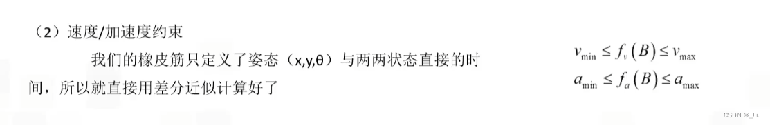
Constrained objective function:


Optimization:
The Teb optimization problem is essentially an optimization problem, where most objectives are locally based and only related to a small set of parameters, since they only depend on a few consecutive robots
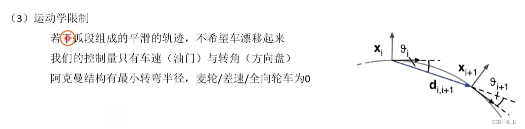
The local trajectory generated by TEB is composed of a series of discrete poses with time information. The goal of g2o algorithm optimization is these discrete poses. At the same time, design a goal with the shortest time, the shortest distance, and away from obstacles, while limiting the speed and acceleration. Make the trajectory satisfy the robot kinematics.
The overall plan is:
Global path———adding constraints———g2o optimization———speed command
parameter:
# Trajectory
teb_autosize: True # Allow changing the length of the trajectory time domain during optimization
dt_ref: 0.3 #local path planning resolution (0.01~1.0) defaults to 0.3 (time_time resolution between two adjacent poses)
(you can set 0.45, others keep the default)
dt_hysteresis: 0.1 #allow floating range
global_plan_overwrite_orientation: True #Overwrite the orientation of local waypoints in the global path
max_global_plan_lookahead_dist: 3.0 #The maximum length of the global optimization subset
feasibility_check_no_poses: 2 # The time interval for detecting poses that can be achieved
# Robot _ The following parameters will actually affect the planning
max_vel_x: 0.7 #Maximum forward speed x (can be set to 0.5 to try)
max_vel_x_backwards: 0.3 #Maximum backward speed x This value cannot be 0 or negative, otherwise it will be wrong
(Cannot prevent reversing, even if the ratio is very large, in unavoidable situations)
max_vel_y: 0.0 # The maximum speed in the y direction Ackermann shape is not available
max_vel_theta: 0.50 #Maximum steering angular speed
acc_lim_x: 0.15 # Maximum acceleration
acc_lim_theta: 0.20 #Maximum angular acceleration, it is not recommended to be too large, it will cause shock
min_turning_radius: 0.35 #Minimum turning radius
The setting of this parameter greatly affects the path planning when turning
footprint_model: # types: "point", "circular", "two_circles", "line", "polygon"
type: "line" # set the robot model - can be the above several
line_start: [0.05, 0.0] # for type "line" #The starting point of the line
line_end: [0.10, 0.0] # for type "line" #The end point of the line
(this line mode is suitable for the Ackerman car, set the starting point and end point of the line)
# GoalTolerance goal tolerance
The first two are more important, but I don't mind setting them small
xy_goal_tolerance: 0.2 #xy target offset degree
yaw_goal_tolerance: 0.2 #target angle offset tolerance
free_goal_vel: True #Allow the robot to go to the destination at the maximum speed, if True, it will accelerate in the process of acceleration
complete_global_plan: True #Complete the target point
# Obstacles obstacles
min_obstacle_dist: 0.30 # Minimum distance from obstacles (head, middle and tail of the entire line)
The setting of this parameter determines the distance from the obstacle constraint
After the test, it is not recommended to set it very small, because our car model itself is small, and there are bumps on the ground, so keep it far away
inflation_dist: 0.30 # Obstacle inflation distance include_costmap_obstacles: True # Whether the real-time obstacles
in the local map are considered costmap_obstacles_behind_robot_dist: 0.3 #The cost map considers the rear obstacles (because there is a reversing car) obstacle_poses_affected: 7 #Obstacle attitude influence, the influence is not Very large dynamic_obstacle_inflation_dist: 0.6 #Dynamic obstacle expansion range include_dynamic_obstacles: True #Whether it will be a speed model costmap_converter_plugin: "" #Generally do not use this plugin costmap_converter_spin_thread: True costmap_converter_rate: 5
#Optimization Optimization Parameters
no_inner_iterations: 5 # The number of executions of the inner loop after being called by the outer loop
no_outer_iterations: 4 # The number of times the outer loop is optimized
optimization_activate: True # Activate the optimization process
optimization_verbose: False # Print the optimization process
penalty_epsilon: 0.1 # approximation for hard constraints
This parameter will be a speed constraint, that is, before reaching the maximum speed, there will be a penalty, which will make him decelerate in advance to achieve the buffer effect
obstacle_cost_exponent: 4
weight_max_vel_x: 2 # Maximum speed weight
weight_max_vel_theta: 1 # Maximum angular velocity weight
weight_acc_lim_x: 1 # Maximum acceleration Weight
weight_acc_lim_theta: 1 # maximum angular velocity weight
(The above parameters mainly play a comprehensive role to determine whether it is high speed or low speed)
weight_kinematics_nh: 1000
weight_kinematics_forward_drive: 500 #Suppress the weight of reversing, the normal setting is 1
weight_kinematics_turning_radius: 1 #Minimum turning radius, we don't need minimum turning
weight_optimaltime: 500 #Optimize time parameters, let the car go straight and inside more.
weight_shortest_path: 0
weight_obstacle : 50 # Weight of minimum distance to obstacles during optimization
weight_inflation: 0.2 # Inflation area weight
weight_dynamic_obstacle: 10 # Dynamic obstacle minimum distance weight
weight_dynamic_obstacle_inflation: 0.2 # Dynamic obstacle inflation area weight
weight_viapoint: 1 # Path sampling point distance weight
The above parameters are the parameters that we modify more and have a greater impact.
important point:
1. When the car is stuck in a certain position and dare not go (it hasn't hit yet), consider whether the expansion radius should be reduced, and whether weight_optimaltime should be increased.
2. At the beginning of the adjustment, the speed can be adjusted slower, and the max_global_plan_lookahead_dist (forward planning distance) can be reduced to make the local path closer to the global path and complete the running map, and then slowly increase it to find the best value

The current situation:
When I set the optimal time to the maximum, the car likes to go in a straight line, but I don’t know if it’s a problem with the construction of the map, or a problem with the car itself. It is easy to get stuck under the track pole, which directly leads to radar There are problems with scanning, and path planning sometimes makes mistakes. I initially think that this is a problem with the construction of the map. The construction of the map is a bit crooked.
But the more fatal problem is that the car always likes to get stuck in the curve, too close to the inner curve, the minimum distance of the static obstacle and the expansion distance set before have little effect, I don't understand it, and then replace the radar to improve it The scanning accuracy, and then the turning angle, does not need to be set too large. We are slowly looking for a suitable turning angle in the process of adjusting the map.
I think the main problem now is to expand the scope of the expansion, so that the car should try not to take the small road, and the setting of the cost map, which is related to the expansion above, so our first thing is to set this up. , the current shortest path does not need to be considered too much, try to stay away from obstacles.
You can try to adjust the nearby range

Increase the local map range to 4*4,
The following is the common file, which is the parameters shared by the global and local cost maps
#---(in meters)---
footprint: [ [-0.035,-0.1], [0.18,-0.1], [0.18,0.1], [-0.035,0.1] ] #设置小车大小
#这个可以根据实际设计,但是我认为可以更大一点,给小车预留一些空间


transform_tolerance: 0.2

obstacle_layer:
 enabled: true
 obstacle_range: 2.5
 raytrace_range: 3.0
 inflation_radius: 0.05
 track_unknown_space: false
 combination_method: 1

 observation_sources: laser_scan_sensor
 laser_scan_sensor: {data_type: LaserScan, topic: scan, marking: true, clearing: true}


inflation_layer:
  enabled:              true
  cost_scaling_factor:  10.0  # exponential rate at which the obstacle cost drops off (default: 10)
  inflation_radius:     0.1  # max. distance from an obstacle at which costs are incurred for planning paths.

static_layer:
  enabled:              true
  map_topic:            "/map"
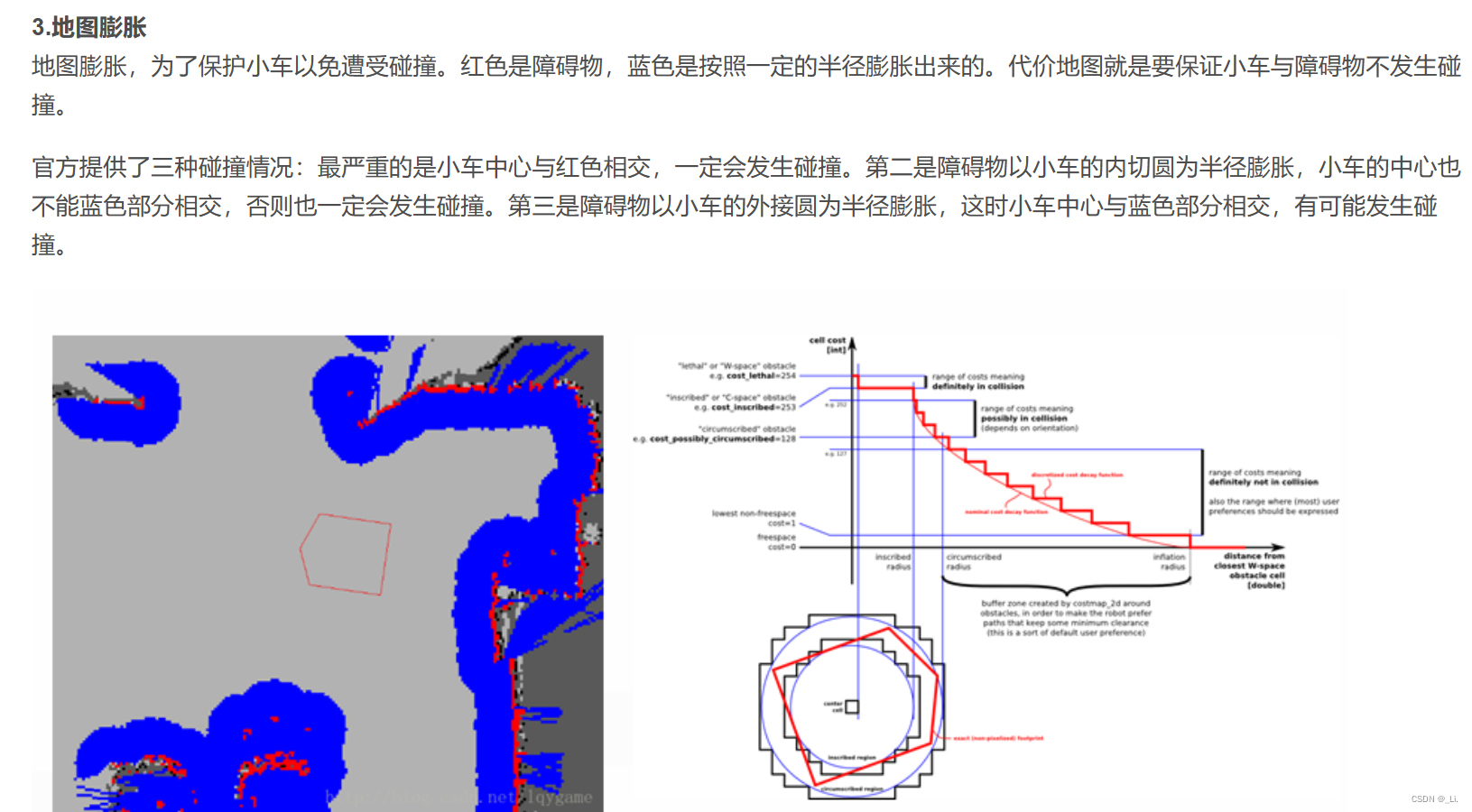
According to the above we pay attention to the following parameters
inflation_radius: 0.05
This is the radius of the obstacle expansion, which should be set to the minimum distance between the obstacle and the car so that it does not take the path, but in order to prevent the path of the car from being stuck (the obstacle is in the middle, the expansion is too large and it coincides with the left and right expansion, resulting in failure In the past), if it is too small, it will cause problems when walking on small roads and turning. This is what we need to pay attention to, so it is currently set to 0.30
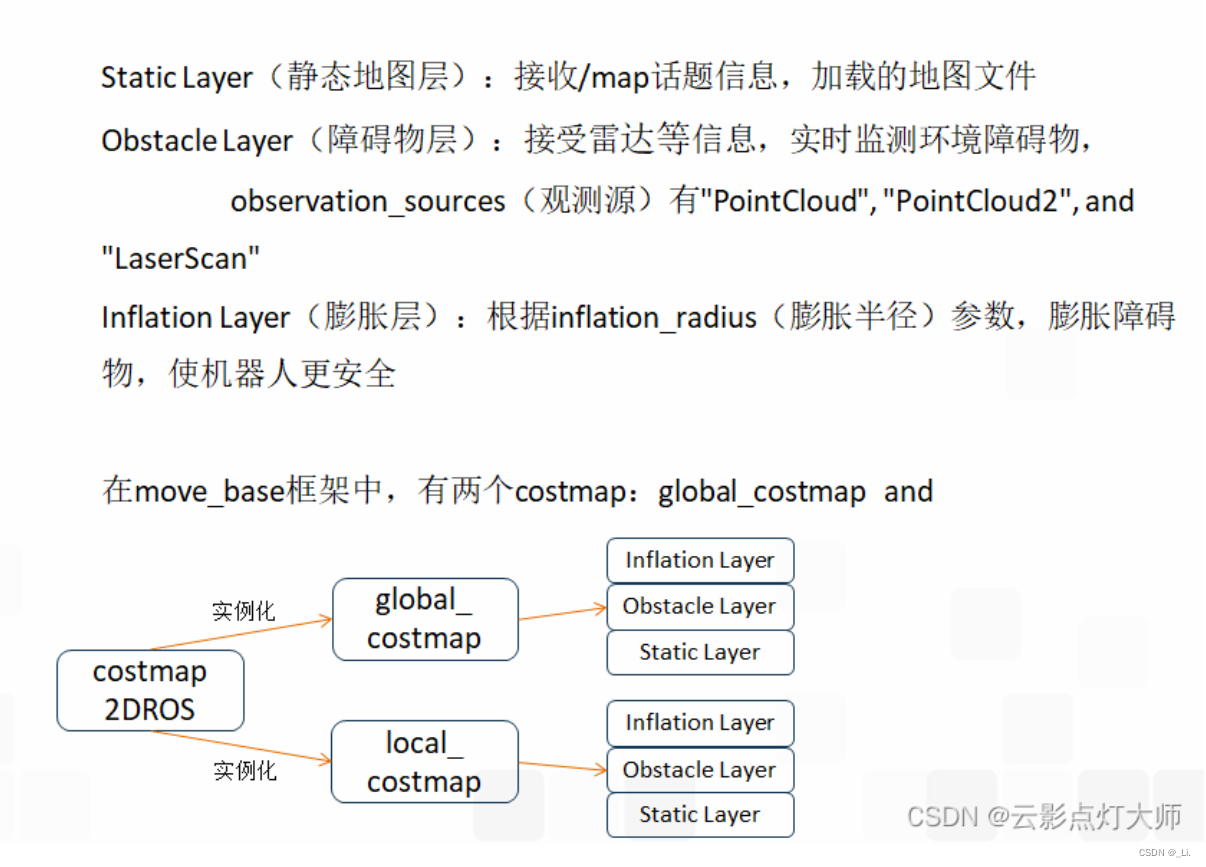
global_costmap需要遵循的配置
global_costmap_params.yaml
global_costmap:
global_frame: /map
robot_base_frame: base_link
update_frequency: 5.0
static_map: true

local_costmap需要遵循的配置
local_costmap_params.yaml
local_costmap:
global_frame: odom
robot_base_frame: base_link
update_frequency: 5.0
publish_frequency: 2.0
static_map: false
rolling_window: true
width: 6.0
height: 6.0
resolution: 0.05
Next try modifying:
inflation_radius: 0.30 under the common file
max_vel_x: 0.7
max_vel_x_backwards: 0.2
max_vel_y: 0.0
max_vel_theta: 0.40 # Prevent excessive shock
acc_lim_x: 0.2
acc_lim_theta: 0.2
min_turning_radius: 0.375 # Minimum turning angle, this needs to be adjusted slowly
xy_goal_tolerance: 0.5
yaw_goal_tolerance: 0.4 # It doesn't matter if the tolerance of position and angle is large.
free_goal_vel: True # Can sprint freely
min_obstacle_dist: 0.30 # Minimum distance from obstacles (head, middle and tail of the entire line)
# What I am curious about is a small question. Is there no relationship between the expansion of obstacles and the map itself, or is this calculated independently, and we need to try again
weight_kinematics_nh: 1000
weight_kinematics_forward_drive: 500 #Suppress the weight of reversing, the normal setting is 1
weight_kinematics_turning_radius: 1 #Minimum turning radius, we don't need minimum turning
weight_optimaltime: 500 #Optimize time parameters, let the car go straight and inside more.
weight_shortest_path: 0
weight_obstacle : 50 # Weight_inflation of minimum distance to obstacles during optimization weight_inflation
: 1 # Inflation area weight I forgot what the maximum is, these avoid obstacles are slightly increased
weight_dynamic_obstacle: 10 # Dynamic obstacle minimum distance weight weight_dynamic_obstacle_inflation
: 0.2 # Dynamic obstacle inflation area Weights