Table of contents
Understanding the Seven-Layer Model
Layer-by-layer encapsulation and layer-by-layer unpacking of data packets
Data and protocols of each layer
Encapsulates a numeric representation of the protocol used
Digital Signal Characteristics
Three basic problems of the data link layer
protocol
Foreword: The emergence of the Internet has completely changed people's way of life. People can shop, chat, watch movies, buy tickets, go to work, etc. without leaving home. However, the transmission of data from one device to another requires network protocols; without network protocols, there would be no Internet today
Meaning: A rule inside the computer, which stipulates how to identify each other when two devices communicate, how to establish a connection, the type of signal used, the encoding and decoding method of data, the type of data transmission, the method of data transmission and the physical level The voltage and current maintenance and cut-off time, etc. stipulate that the two devices can only communicate with each other only if the protocol is exactly the same or compatible.
example
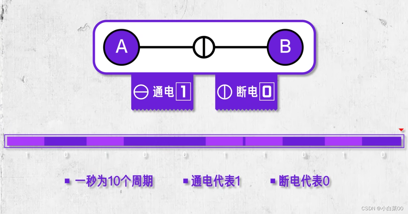
Assume that there is a circuit between A and B components, which can be powered on and off. If we do not make any regulations and constraints, then this bus will not be able to achieve any functions except that it can be powered on and off. If we stipulate a The second is 10 cycles, the power-on is 1, and the power-off is 0; then A only needs to go through a large number of power-on and power-off to transmit the information he wants to send to B at a speed of 10 bits per second; and this is 10 per second. Period, power on means 1, power off means 0. This regulation is the communication protocol between A and B.
Understanding: A protocol is a system or regulation in which the two parties agree in advance to use a certain form, a certain specification, and a certain object to transmit data, and the other party accepts the data with the same rules and procedures.
OSI seven layer model
Preface: Since there was no unified standard for the use of private network models by early computer manufacturers, ISO promulgated the OSI reference model in 1984, which divided the network into seven layers.
Definition: The OSI seven-layer model (Open System Interconnect), called the Open System Interconnection Reference Model, is an open system interconnection reference model jointly developed by the International Organization for Standardization (ISO) and the Consultative Committee for International Telegraph and Telephone (CCITT). An information system provides a framework for a functional structure.
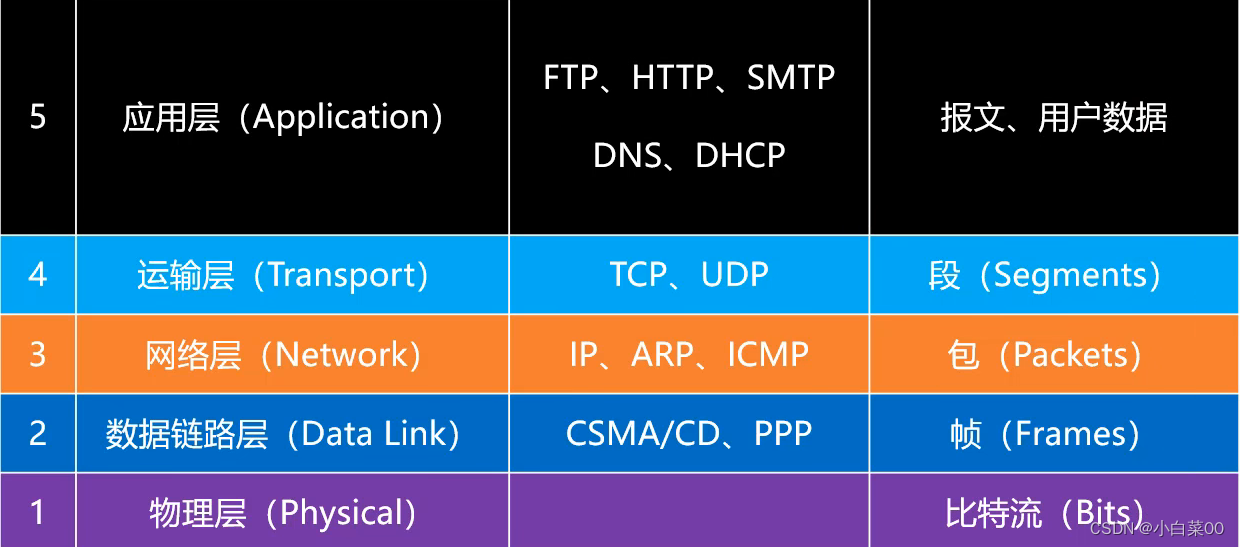
Understanding the Seven-Layer Model
- Application layer: Convert raw data into binary data that computers can recognize
- Presentation layer: data representation, encryption, compression, etc.
- Session layer: establish, manage, terminate sessions (software level)
- Transport layer: defines the protocol, port number, flow control, and error checking of data transmission
- Network layer: addressing of logical addresses (IP addresses) to realize path selection between different networks
- Data link layer: establish logical connection, address hardware address (MAC address), error check
- Physical layer: Binary data is converted into electrical and optical signals for transmission (establish, maintain, and disconnect physical connections)
The following is the process of layer-by-layer data encapsulation and data layer-by-layer decapsulation of the OSI seven-layer model

Note: In each layer, a header will be attached to the sent data, which contains the necessary information of the layer, such as the destination address and protocol related information. Usually, the information provided for the protocol is the packet header, and the content to be sent is the data. From the perspective of the next layer, all the packets received from the upper layer are considered as the data of this layer.
TCP/IP Reference Model
Preface: The OSI reference model is just a standard, and the organization that formulates this standard is often too theoretical. However, in the actual application process, it is gradually found that the TCP/IP protocol model is practical (in the actual application process, this TCP/IP The model is in line with real life); only the TCP/IP protocol with four-layer architecture is much simpler than OSI with seven-layer architecture. Higher, lower cost.

Note: Of course, some textbooks usually divide the network interface layer into two layers (data link layer, physical layer) for the sake of research clarity, so that the TCP/IP model has a five-layer structure
Layer-by-layer encapsulation and layer-by-layer unpacking of data packets

Data and protocols of each layer
Encapsulates a numeric representation of the protocol used

physical layer
Preface: The physical layer defines the interface standard, cable standard, transmission rate, transmission mode, etc.
analog signal

Analog Signal Characteristics
- The analog signal is a continuous signal, suitable for long-distance transmission
- The analog signal has poor anti-interference ability, and the waveform deformation is difficult to correct when it is interfered
Digital signal

Digital Signal Characteristics
- Digital signals are discrete signals, not suitable for long-distance transmission
- The digital signal has strong anti-interference ability, and the waveform distortion can be repaired when it is interfered
Data Communication Model

channel
Meaning: the channel for information transmission, there can be multiple channels on one transmission medium (such as a network cable)
way of communication
- Simplex communication: The signal can only be transmitted in one direction, and the transmission direction of the signal cannot be changed at any time
- Half-duplex communication: Signals can be transmitted in both directions, but must be carried out alternately, and can only be transmitted in one direction at the same time.
- Full-duplex communication: one channel allows two-way data transmission at the same time
data link layer
Link: A stretch of physical line (wired or wireless) from one node to an adjacent node, with no other switching nodes in between

Notice:
- A hub does not count as a link node
- When transmitting data on a link, a corresponding communication protocol is required to control the transmission of data; the communication protocols used by different types of data links may be different
- The broadcast channel uses the CSMA/CD protocol (such as a network composed of coaxial cables, hubs, etc.)
- Point-to-point channels use the PPP protocol (such as a channel between two routers)
Three basic problems of the data link layer
- Encapsulation and framing
- Transparent transmission
- error checking
Encapsulation and framing

Notice:
- Each data link layer specifies the upper limit MTU of the data length of the frame that can be transmitted (Ethernet's MTU is 1500 bytes)
- During the encapsulation and framing process of the data link layer, content is added to the header and tail of the Internet layer packet, and the added content is related to the type of link (the protocol used by the link)
Transparent transmission
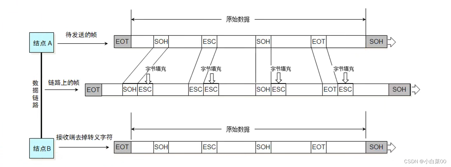
Preface: Because the data frame has a frame start symbol (SOH) and a frame end symbol (EOT), once the data part appears SOH, EOT, ESC, it needs to be escaped (add ESC characters to fill in)
error checking
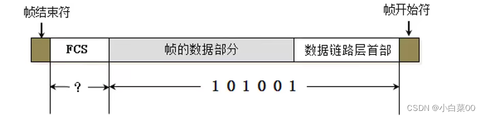
There is an FCS at the end of the frame, which is mainly used for error checking
FCS function: If the data is transmitted in the channel, if it is subject to some interference signals, it may be distorted, so the transmitted data may be inaccurate. To check the integrity of the data, the network card will get the frame data part and the data link layer header and send them Calculate a value, the calculated value is called FCS, if the network card compares the two FCSs to be the same, then the data is not distorted during transmission; if the network card compares the two FCSs to be different, the network card will discard the data
CSMA/CD agreement
Understanding: Carrier Sense Multiple Access/Collision Detection
- Carrier Sense: A device in the hub can monitor whether there is a signal transmitting on this channel. If it detects that there is no signal transmitting on this channel, it will send the signal if necessary, otherwise it will not send the signal
- Multiple access: all devices in the hub can send signals
- Conflict detection: If two devices in the hub listen to the channel without signal transmission at the same time, and send out the signal at the same time, the two signals will conflict, and the signal will rebound after the collision. At this time, the device has the ability to judge the response. Is the bounced message a reply message from someone else or a rebound message generated by a conflict
Notice:
- The network using the CSMA/CD protocol can be called Ethernet, and it transmits Ethernet frames
- Ethernet frame formats are (Ethernet V2 standard, IEEE802.3 standard) the most commonly used is the Ethernet V2 standard
- The network built with switches already supports full-duplex communication, and there is no need to use the CSMA/CD protocol, but it still transmits Ethernet frames, so the network built with switches can still be called Ethernet
- In order to be able to detect whether the frame being sent has a collision, the Ethernet frame must be at least 64 bytes
Format of Ethernet V2 frame

Notice:
- Because Ethernet uses Manchester encoding, as long as there is no signal transition at the receiving end when receiving a frame, the frame is considered to be over, so there is no frame start and frame end delimiter
- When transmitting at the physical layer, a preamble and a frame start symbol need to be inserted. The main purpose of the preamble is to help the receiver perform time and frequency synchronization, and to tell the receiving station that the next frame is coming and ready.
- The type of 2 indicates the network type (IPV4, IPV6)
- The data of the IP data packet is at least 46, and the maximum is 1500. When the length of the data part is less than 46 bytes, the data link layer will add some bytes to the end of the data. When the data is received, the receiving end will fill it byte removed
PPP agreement
Meaning: (point to point protocol) point-to-point protocol

PPP protocol byte padding

Notice:
- PPP protocol frame format has frame start and frame end symbols: 0x7E
- The A of the header is the Address field, the value in the figure is 0xFF, which is useless, and the point-to-point channel does not require source mac and target mac
- The C in the header is the Control field, the value in the figure is 0x03, which is useless at present
- The Protocol field is the protocol type used internally
network card
Meaning: Also called a network adapter, the network card is an indispensable part of the computer's Internet access. Its position in the computer network is the data link layer and the physical layer, taking into account the functions of the two layers.
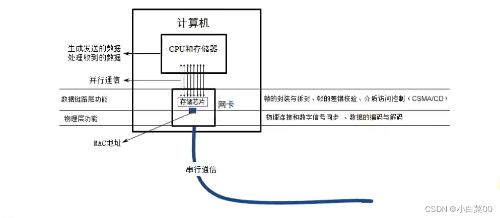
The role of the network card: the main function of the network card is the function of the physical layer and the data link layer, which is the encapsulation and decapsulation of data, link management, encoding and decoding; the communication between the network card and the computer is through the computer motherboard . The I/O bus is transmitted in parallel . If our network card needs to communicate after it is connected to the network, we need to configure an ip address for it.
Notice:
- Each network card has an identity (MAC address), which is globally unique and stored in the ROM of the network card
- When the network card receives a frame, it will first check the error, if the check passes, it will receive it, otherwise it will be discarded
- The frame captured by wireshark has no FCS, because it captures the frame that passed the error check (the FCS at the end of the frame will be removed by the hardware)
- Wireshark can't capture the frame that failed the error check