For more graphics knowledge, please pay attention to my public account:

foreword
What is the computer for?
A computer is also called a computer, so the most important job is calculation. Students who have seen the three-body problem know that there are countless nanometer-level calculation units in the computer, and the operations of addition, subtraction, multiplication and division can be completed through the conversion of 0 and 1.
What makes a computer work?
Drivers drive the hardware to do the work.
Who will write the driver?
Companies that make computers write their own drivers because they are most familiar with their underlying hardware architecture.
Who will use the driver?
All software engineers will directly or indirectly use the driver.
Then the problem comes, if different computer companies manufacture different hardware, use different drivers, and provide different interfaces for software engineers to use, then the software engineers will collapse.
Therefore, a standard must be needed to unify it.
So where is the unification?
There is no way to unify the hardware. In order to optimize the performance and power consumption of their computers, each computer company manufactures different hardware architectures. This requires countless efforts to complete. If they are unified, then there will be no need for so many computer companies.
Therefore, only the interface of the driver can be unified.
Computer components are roughly divided into: CPU, GPU, memory, bus, etc. And OpenGL is a set of standard interfaces for GPU drivers (OpenGL ES is a standard interface for GPU drivers for embedded devices, such as mobile phones, the full name of OpenGL ES: OpenGL for Embedded Systems).
So to sum up, I used 5 questions to draw out the usefulness of OpenGL: it is to package complex and various GPU hardware, each computer company writes its own driver, and then provides a set of unified interface , for upper-level software engineers to call. In this way, the world will be peaceful.
Two friends of OpenGL ES
Two Little Friends of OpenGL ES
Although the title of our tutorial is OpenGL ES, our content will not be limited to OpenGL ES. OpenGL ES is responsible for the work of GPU. The purpose is to obtain a picture through GPU calculation. This picture is actually a buffer in the memory, which stores the color information of each point. And this picture will eventually be displayed on the screen, so it needs a specific window system to operate, and OpenGL ES does not have related functions. So, OpenGL ES has a good partner EGL.
EGL, full name: embedded Graphic Interface, is the interface between OpenGL ES and the underlying Native platform windowing system. So the general process is like this: First, get the handle of the mobile phone screen through EGL, and get the configuration supported by the mobile phone (RGBA8888/RGB565, etc., indicating how many bits of storage space information such as color contained in each pixel is), and then According to this configuration, create a surface containing the default buffer (the size of the buffer is calculated based on the screen resolution multiplied by the size of each pixel information) and a context for storing the OpenGL ES state set, and enable them. Then, operate the GPU to calculate through OpenGL ES, and save the calculation result in the buffer of the surface. Finally, use EGL to display the drawn picture on the mobile phone screen.
When OpenGL ES operates GPU computing, it is also necessary to introduce another good partner of OpenGL ES, GLSL.
GLSL, full name: OpenGL Shading Language, is the shader language used in OpenGL ES, in which small programs can be written to run on the GPU.
Here we need to mention the difference between CPU and GPU. Their functions are used for computing and are composed of many cores. The difference is that CPU has fewer cores, but a single core has relatively strong computing power, while GPU cores A lot, but the computing power of each core is not particularly strong. At present, the main job of the GPU is to generate pictures (now there are high-performance computing_parallel computing through the GPU, but this is not in the scope of discussion here), the reason is that the picture is composed of many pixels, each pixel contains color, Depth and other information, and in order to obtain these information data, the calculation for each pixel point can be completed through a unified algorithm. GPU is good at processing such large-scale data, using the same algorithm for calculation. And this algorithm is written as Shader using GLSL for GPU computing.
From the perspective of graphics, all pictures are composed of triangles. So when drawing a picture through OpenGL ES, we need to create a shader for running on the GPU through the OpenGL ES API, and then transfer the vertex information of the picture obtained through the CPU to the Shader in the GPU. Through matrix transformation in Vertex Shader, the vertex coordinates are converted from the model coordinate system to the world coordinate system, then to the observation coordinate system, to the clipping coordinate system, and finally projected into the screen coordinate system to calculate the coordinates of each vertex on the screen. Then, through rasterization, the information of all pixels is obtained by interpolation, and the color of all pixels is calculated in the Fragment shader. Finally, through the state set by the OpenGL ES API, the obtained pixel information is subjected to depth/stencil test and blend to obtain the final picture.
The nature and generation process of screen pictures
When we buy a mobile phone, we pay great attention to the resolution of this mobile phone. The resolution represents the number of pixels. For example, the resolution of the well-known iphone6 is 1334×750, while the resolution of the iphone6 plus is 1920×1080.
The picture on the mobile phone screen is composed of pixels one by one, so it can be calculated that the picture on a screen is composed of millions of pixels. And each pixel has its own color, and each color is composed of RGB three primary colors. The three primary colors are mixed in different proportions to form the colors that the mobile phone can display.
The color information of each pixel is stored in the buffer. This buffer can be allocated to each channel of RGB with 8 bits for information storage, or it can be allocated to a different space for each channel of RGB for information storage. For example, because the human eye is most sensitive to green Sensitivity, then 6 bits can be assigned to the G channel, 5 bits each for the R and B channels. These are common phone configurations. If you use RGB888 mobile phone configuration, that is, the value of each color is from 0 to 255, with 0 being the smallest and 255 being the largest. Then when red, green and blue are all 0, the color of this pixel is black; when red, green and blue are both 255, the color of this pixel is white. When red is 255 and green and blue are both 0, the color of this pixel is red. When red and green are 255 and blue is 0, the color of this pixel is yellow. Of course, it is not only 0 or 255, it can take the value between 0-255, 100, 200, any value between 0 and 255 is no problem. Then we can calculate, according to the different ratios of red, green and blue, each pixel can display 255 255 255 = 16581375 colors, this number is very scary, so our mobile phone can display a variety of colors color. Here is an extended science popularization. We see that mobile phones can display so many colors, but does it mean that our mobile phones have developed to the extreme in terms of color? In fact, it is far from it. Under this mobile phone configuration, Each of the three primary colors can take a value from 0 to 255, and in real life, they can take a value from 0 to 100 million, while our human eyes can see a range from 0 to 100,000. Therefore, there is still a lot of room for improvement in mobile phone hardware. Before the hardware of the mobile phone is improved, we can also display more colors in the mobile phone as much as possible through technologies such as HDR. So, when it comes to this, we know that the picture displayed on the mobile phone screen is composed of these millions of pixels and the colors corresponding to these millions of pixels.
From a programmer's point of view, the mobile phone screen corresponds to a buffer, and this buffer corresponds to millions of pixels, and each pixel needs a certain amount of space to store its color. If we use a more vivid example to describe it, the buffer corresponding to the screen of the mobile phone is like a huge chessboard with millions of grids, and each grid has its own color. If you look at the chessboard as a whole from a distance, it is It's what we see when we look at our phones. That's the nature of pictures on your phone's screen.
Through our understanding of EGL, GLSL, OpenGL ES, with the help of a picture, explain how the picture on the mobile phone screen is generated from a professional point of view.
First, obtain the mobile phone screen through EGL, and then obtain the chessboard corresponding to the mobile phone screen. At the same time, according to the configuration information of the mobile phone, another chessboard and a notebook are generated in the GPU of the mobile phone. The notebook is used to record the initial color of the chessboard, etc. information.
Then, OpenGL ES is like a programmer's paintbrush. Programmers need to know what they want to draw. required model. For example, use several triangles, points and lines to approximate the composition of the apple (the fundamentals of graphics are points, lines and triangles, all graphics can be composed of these basic graphics, such as a square or a rectangle, it can be composed of two triangles A circle can be composed of countless triangles, but the more triangles there are, the rounder the circle looks).
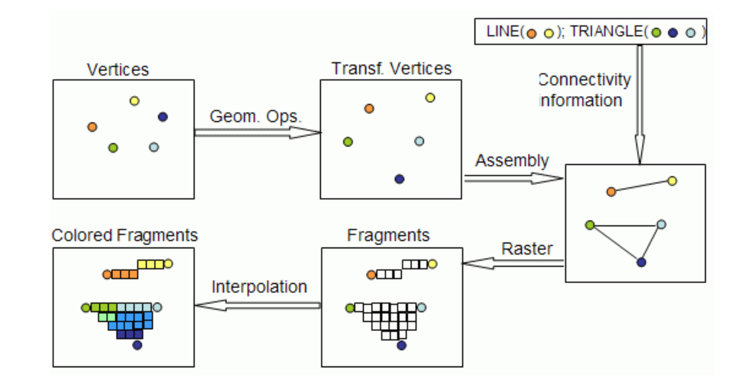
According to these geometric primitives, establish a mathematical description, such as the vertex coordinate position of each triangle or line, and the color of each vertex. After getting this information, you can first initialize the color of the chessboard (buffer) generated by EGL through OpenGL ES, usually it will be initialized to black. Then, the vertex coordinates we obtained just now are transformed into models, observations, and projections through matrix changes, and finally mapped to the screen to obtain the coordinates on the screen. This step can be done in the CPU, that is, before OpenGL ES transmits the coordinate information to the Shader, it is updated in the CPU by matrix multiplication, or directly transmits the coordinate information to the Shader through OpenGL ES, and at the same time, the matrix The information is passed to the Shader, and the coordinates are updated on the GPU side through the Shader, and the updated algorithm is written in the Shader through GLSL. The Shader for updating coordinates is called vertex shader, or VS for short, which is OpenGL ES2.0 and one of the most important two shaders corresponding to GLSL130 version. Its function is to complete all operations in the vertex operation stage. The pixel coordinate information after matrix transformation is the coordinate information in the screen coordinate system. In VS, the most important input is vertex coordinates and matrix (you can also pass in vertex color, normal, texture coordinates and other information), and the most important calculation result is the coordinate information that will be displayed on the screen. VS will operate on all vertices passed in. For example, in OpenGL ES, you only want to draw a triangle and a line. These two primitives do not share vertices. Then in VS, 5 vertex information is passed in. According to Matrix transformation, the coordinates of these 5 vertices are converted into the vertex coordinate information on the screen, which is displayed on the picture, that is, from picture 1 in the upper left corner, it is updated to picture 2 in the upper middle picture.
Then, when Figure 2 is generated, we know the vertex position of the primitive on the screen, and the color of the vertex does not change in VS, so we also know the vertex color of the primitive. The following is to indicate which points are connected into lines and which points form triangles according to the state set in OpenGL ES, and the primitives are assembled, which is what we see in Figure 3 in the upper right corner. This look will not be displayed on the GPU, and those lines are also virtual lines, which will not be displayed in the checkerboard buffer. What the GPU does is smoothing, and this step occurs when it comes out of VS and enters another Shader (Pixel shader, also known as fragment shader) before, in the GPU. The function is to find all the pixels on the line or inside the triangle, and calculate its color and other information according to interpolation or other methods (if you do not use interpolation, you can use other methods, which can be set in OpenGL ES and GLSL ). It also generates Figure 4 and Figure 5 in the row below.
We can probably see that there are a lot of vertices in Figure 4 and Figure 5. It is estimated that there are about 40 points. All these points will be entered into PS for operation. In PS, the color of these points can be operated. For example, only the red channel of these points can be displayed, and the values of the other green and blue channels are set to 0. For example, the RGB of a certain point before is 200, 100, 100. It can be updated to 200,0,0 through calculation in PS. The result of this is that the displayed pictures are all red, but with different shades. This is like wearing a red filter, and other colors are filtered out. So it is very convenient to use PS as a filter. For another example, if a red light shines on an apple, then the displayed color is based on the original color of the apple, and the red value is increased to a certain extent.
So, to sum up, after VS and PS, what the programmer wants to draw has already been drawn. The thing I want to draw is the one shown in Figure 5 in the lower left corner. Then, according to the settings of OpenGL ES, perform Depth/Stencil Test on the newly drawn things, remove the occluded parts, blend the remaining parts with the original picture, and generate a new picture. Finally, through EGL, exchange the generated chessboard buffer with the corresponding chessboard buffer on the mobile phone screen, let the mobile phone screen display the newly generated chessboard, and draw the new picture information on the old chessboard. Going over and over again, switching the chessboard constantly, just like watching comics in the past, the animation is composed of pictures one by one. When the number of pictures switched per second exceeds 30, our mobile phone will also see the dynamic Effect. This is how the picture on the screen is produced.
Here is another extension. In this example, VS calculates the data of 5 vertices, and PS calculates the data of about 40 vertices. As we just said, there are millions of pixels in the mobile phone. Every pixel can be a vertex, so the amount of calculation is very large. And that's why you put shader operations in the GPU, because GPUs are good at doing them.
We know that CPUs are now generally dual-core or 4-core, most of which are 8-core or 16-core, but GPUs are often 72-core, and there are thousands of cores. The purpose of so many cores is to perform parallel computing. Although a single GPU The core is not as good as the CPU core, but a single GPU core is sufficient for addition, subtraction, multiplication, and division operations, so a large number of GPU cores are used in graphics pixel operations, which is very effective. Although a single CPU is very powerful, and can also improve throughput through multi-stage pipelines, it is still not as fast as the multi-core GPU. However, when performing multi-core calculations through the GPU, it should be noted that if the judgment statement is stored in the shader, it will cause a relatively large load on the GPU. Different GPUs have different implementation methods, and most GPUs will treat both cases of the judgment statement. Carry out calculations, and then choose one of them according to the judgment result.
Through this example, we once again cleared the entire process of OpenGL ES drawing, and this example is also the simplest example, in which many other operations of OpenGL ES are not involved. For example, the color of the object we draw is mostly sampled from the texture, so it is designed to operate on the texture through OpenGL ES. And these functions of OpenGL ES, we will learn bit by bit below.
OpenGL ES pipeline
EGL is used to deal with mobile devices, such as obtaining the drawing buffer and displaying the drawing buffer on the mobile phone screen. So aside from EGL, the main function of OpenGL ES and GLSL is to draw pictures on this buffer.
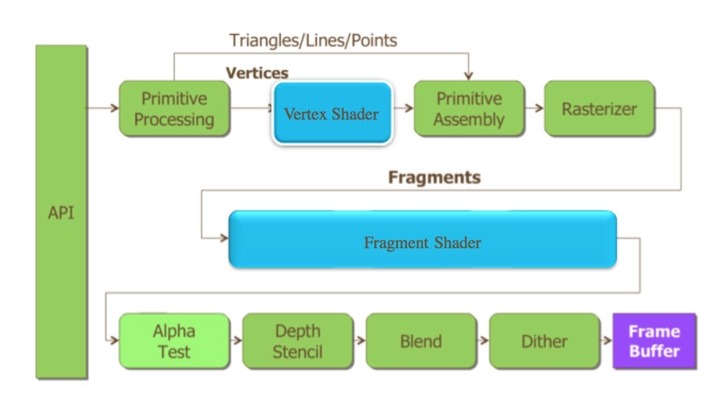
Therefore, we can separate the processes of OpenGL ES and GLSL for summary, and this flow chart is the famous OpenGL ES2.0 pipeline.
First of all, the leftmost API refers to the API of OpenGL ES. OpenGL ES is actually a graphics library consisting of 109 APIs. As long as you understand the meaning and use of these 109 APIs, you can master OpenGL ES 2.0.
Then, we first set the vertex information, vertex coordinates, index, color and other information through the API, and pass these information into VS.
Perform calculations in VS to get the final vertex coordinates. Then assemble the primitives with the calculated vertex coordinates to construct virtual lines and triangles. Then perform lightening (when lightening, connect the vertices to form a straight line, or fill a polygon, you need to consider the line width of the line and polygon, the size of the point, the gradient algorithm, and whether to use coverage that supports anti-aliasing Algorithm. Each pixel in the end has its own color and depth value).
Pass the lightening result to PS for final color calculation.
Then, before the so-called final result is actually stored in the drawing buffer, a series of operations are required. These operations may modify or even discard these pixels.
These operations are mainly alpha test, Depth/Stencil test, Blend, Dither.
Alpha Test adopts a very domineering and extreme mechanism. As long as the alpha of a pixel does not meet the conditions, it will be discarded by the fragment shader. The discarded fragments will not affect the various tests behind; otherwise, it will be normal Proceed to the following test. The effect produced by Alpha Test is also very extreme, either completely transparent, that is, invisible, or completely opaque.
Depth/stencil test is easier to understand. Since we are drawing 3D graphics, the coordinates are XYZ, and Z is generally the depth value. OpenGL ES can set the depth test, such as setting the depth value to be discarded. The depth value is 0, and the depth value of the pixel output by PS is 1, then the pixel output by PS is discarded. The stencil test is simpler, and it is also called a mask test. For example, you can set different stencil values through OpenGL ES. If the stencil value of a pixel on the drawing buffer is 0, and the pixel output by PS If the stencil value is 1, the pixels output by PS will be discarded.
Now that we talked about Depth/stencil, let's talk about how big the drawing buffer is and how much information it stores. According to what we just said, a mobile phone can support one million pixels, so the generated drawing buffer needs to store the information contained in the million pixels, and the information contained in each pixel is related to the configuration of the mobile phone. If the mobile phone supports Depth/stencil. Then, in the drawing buffer obtained through EGL, each pixel contains RGBA color value, depth value and stencil value, where each component of RGBA generally occupies 8 bits, that is, 8bit, that is, 1byte, and depth mostly occupies 24 bits, stencil occupies 8 bits. So each pixel occupies 64bit, which is 8byte. Then the size of the drawing buffer of iphone6 plus is 1920×1080×8=16588800byte=16200KB=15.8MB.
There is also blend below, and the blend blending mode can be set through OpenGL ES. Since each pixel in the drawing buffer already has a color, how to mix the output color of PS with the color in the drawing buffer to generate a new color and store it in the drawing buffer is set through blend.
The last dither, dither is an image processing technique that intentionally creates noise to randomize the quantization error and prevent problems like banding (color bands) caused when the image is greatly pulled up. It can also be turned on or off through OpenGL ES. (Patrick: Dither still needs to open another topic to talk about it)
After this series of operations and tests, the final pixel information is obtained, and after storing it in the drawing buffer, the pipeline of OpenGL ES is over.
In the whole pipeline, the vertical line is operated according to the assembly line, and the horizontal line is operated according to the independent operation. Multi-level parallelism improves rendering performance.
Overview of the OpenGL ES API
As we have just said, OpenGL ES is a graphics library consisting of 109 APIs. In the following tutorials, we will explain these 109 APIs in detail. Here we first introduce what these 109 APIs do.
First, there are 9 APIs for creating drawing buffers from the phone. Although EGL will provide OpenGL ES with a drawing buffer, which will be displayed on the screen later, OpenGL ES can also generate one or more buffers according to custom configuration, and can draw some content to these spares first. buffer, and then according to certain processing, finally draw the formal content to the real drawing buffer, and then display it on the screen. Or you can directly display the content in the spare buffer to the screen. Generally more complex graphics programs will use these APIs.
Then, there are 12 APIs for communicating with GPU programmable module Shader. According to what we said above, we talked about the concept of shader. Shader is created by OpenGL ES. From the perspective of OpenGL ES, shader is similar to a handle; then write content to shader through OpenGL ES; trigger GPU to compile Shader; after successful compilation, a VS and a The PS is connected together and bound to another handle called program; enabling this program through OpenGL ES is equivalent to enabling two compiled shaders bound to the program for calling by the GPU.
Afterwards, there are 27 APIs for transferring drawing information, such as transferring vertex information, matrices, and texture images from the CPU to the GPU through the API. There are many ways to pass in, and we will explain them one by one later.
Afterwards, there are 30 APIs for setting the drawing state. OpenGL ES is also known as the state set, because it is constantly setting various states for the GPU to call, such as setting whether to mix colors and how to mix them, such as Set whether depth, stencil and other tests are needed, and how to test.
Secondly, there are 2 APIs, which are used to execute drawing commands, that is, when executing this API, the information previously passed to the GPU is associated together. In this API, you can set which vertices are used for drawing, and how to assemble these vertices into primitives, etc.
There are also 25 APIs, which are used to query the environment and clean up the state. Since OpenGL ES is a state set, basically all state information can be queried. Even if we have not set them, these states will have default values. Get these Status information can be more beneficial to help us make judgments.
Finally, there are 4 APIs for other purposes, and we will introduce them one by one when we talk about them.