Broken thoughts: Long time no see, I miss you so much! This issue brings the content about ZYNQ7020. We know that ZYNQ is a SOC with a hard core, and the PS side is very powerful, which can realize some algorithm verification more conveniently. This article explains the TTC timer in detail, and the Part2 released later will be based on specific projects to realize six channels of PWM output with unequal duty cycles on a single core at the PS end~
Although it didn't seem to help QAQ for my graduation in the end, after all, I spent some time reading the manual and other content, so I plan to record it for your reference.
Table of contents
1.3.2 Event Timer/Pulse Width Counter (Event Timer) Operation
1.5.1 Steps to enable the counter
1.5.2 Procedure for counter stop
1.5.3 Procedure for Counter Restart
1.5.4 The steps to enable the event counter (pulse width counter)
1.5.5 Procedure for Clearing Interrupts and Acknowledgments
1.6 Selection of counter clock input
1. Set up the interrupt system: SetupInterruptSystem()
2. Set the Ticker timer: SetupTicker()
3. Set the PWM timer: SetupPWM()
4. Gradually modify the duty cycle: WaitForDutyCycleFull()
5. Stop the counter: XTtcPs_Stop()
1 Analysis of TTC principle
In this part, we analyze and introduce directly according to the ideas of UG585. Since the content of the original text itself is in English, it still needs some experience to understand (although it is recommended to read the original part).
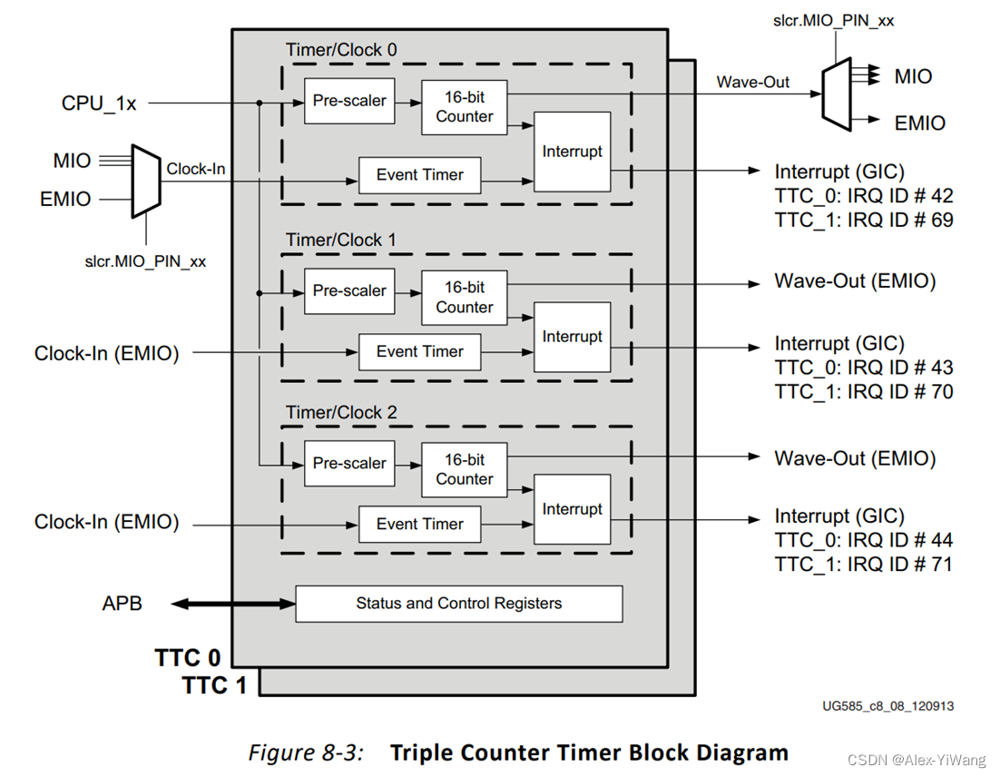
TTC contains three independent timers, which are Timer/Clock 0, Timer/Clock 1, and Timer/Clock 2 in the above figure. From the lower left corner, you can see that there are two TTCs on the PS side, namely TTC0 and TTC1, so the two TTCs contain 6 independent timers in total. The TTC controller can switch between secure mode and non-secure mode by modifying the bits of the register nic301_addr_region_ctrl_registers.security_apb [ttc1_apb]. For the content of these two modes, please refer to the following:
Secure mode and Non-secure mode:
These two modes are derived from the ARM TrustZone technology. ARM introduces a special CPU mode called "safe mode" outside the normal mode of the CPU, and establishes the "safe world" and "normal world" concept. By default, the secure world accesses all state of the normal world, but not vice versa. Since ARM basically uses a structure based on memory mapping, my understanding is to realize the protection of important registers through the separation of these two modes.
1.1 Main Features
Each TTC has the following characteristics:
1. Three independent 16-bit prescalers and 16-bit up/down counters. (Up: 0, 1, 2, 3, 4... Down: 9, 8, 7, 6...)
2. Optional clock source input (internal PS bus clock: CPU_1x, internal clock: PL, external clock: MIO)
3. For each counter inside the TTC, there is an interrupt
4. An overflow interrupt within a certain interval, or an interrupt will be issued when the count matches the set value
5. Generate waveform output, which can be through MIO or PL (EMIO)
1.2 Structural block diagram
Through the above structural block diagram, the multi-channel control of the clock input and waveform output signal of the first counter Timer/Clock 0 in TTC is realized through the slcr.MIO_PIN_xx register, and the EMIO interface is used by default.
1.3 Functional description
Each prescaler module (Pre-scaler) can be independently set to use the PS internal bus clock or external clock (from MIO or PL). For external clock input, select specific signal input by using SLCR register. The prescaler module can divide the input clock between /2 and /65536. When the frequency division register is 0, the frequency of the clock will be divided by two, and then output to the following counter.
The timer can be set to count up and count down, and the range of counting can be controlled by setting the value of the interval register. At the same time, the value of the three matching registers can be compared with the value of the counter (a TTC contains 3 counters and 3 sets of matching registers), and an interrupt signal is generated.
The interrupt module combines various types of interrupts: counter interval interrupt (Interval Interrupt), counter match interrupt (Match Interrupt), counter overflow interrupt (Overflow Interrupt), event timer overflow. Each type can be enabled individually.
1.3.1 Operating modes
Each counter module in a TTC can be independently programmed and run in either of the following two modes.
Interval mode:
By modifying the DEC bit of the counter control register (Counter Control register), you can control whether the counting direction of the counter is +1 or -1. By modifying the value of the interval counter (Interval mode), the range of counting can be controlled from 0 to the value of the interval counter. When the count value passes 0, a counter interval interrupt (Interval Interrupt) will be generated. When the value of the counter is equal to the match counter (Match register) value, a match interrupt (Match Interrupt) will be generated.
Overflow mode:
The counter changes continuously between +1 or -1 between 0x0000 and 0xFFFF, and the direction of counting is controlled by modifying the DEC bit of the counter control register. When the count value passes 0, an overflow interrupt (Overflow Interrupt) will be generated. When the counter value is equal to the match counter value, a match interrupt will be generated.
1.3.2 Event Timer/Pulse Width Counter (Event Timer) Operation
From the name of the pulse width counter, it can be inferred that its function is to measure the pulse width of the external input signal. The principle is similar to the M method speed measurement of the motor differential encoder.
There is a 16-bit internal counter (Internal Counter) invisible to the user inside the event timer. This counter is controlled by the clock of CPU_1x, which meets the following two conditions:
1. When the external pulse is not in the counting phase, it is reset to 0
2. During the counting phase of the external pulse, start to increase
Modify the event timer to control the behavior of the internal counter, which is mainly controlled by three bits:
1 E_En bit Enable bit, when equal to 0, reset the internal counter to 0 and stop counting
2 E_Lo bit specifies the counting phase of the external pulse
3 E_Ov bit specifies how to handle when the internal counter overflows.
When it is 0, the overflow causes E_En to be set to 0;
When it is 1, the overflow causes the internal counter to continue counting in a loop;
Under the control of another register, it is possible to decide whether to generate an interrupt on overflow (regardless of the value of the E_Ov bit itself).
When the count phase of the external count pulse ends, the value of the event register (Event Register) is updated with the non-zero count value of the internal counter. Therefore, this value shows the width of the external pulse. Since the internal counter is clocked by CPU_1x, the pulse width is measured by the number of clock cycles of CPU_1x.
During the count phase of the external count pulse, if the internal counter is reset to 0 due to overflow, the event register will not be updated and will keep the old value of the last non-overflow count operation.
1.4 Register overview
| Function |
name |
overview |
| clock control |
Clock Control Register |
Control prescaler, select clock input, select edge |
| Counter Control Register |
Enable counter, set operation mode, set count direction, enable match, enable waveform output |
|
| state |
Counter Value Register |
Returns the current value of the counter |
| counter control |
interval register |
set interval value |
| match register 1 match register 2 match register 3 |
Set the matching value, there are 3 groups in total, corresponding to 3 Counters inside a TTC (this statement is not accurate, in fact, each Counter has its own set of three matching registers) |
|
| to interrupt |
interrupt register |
Show current interrupt status |
| interrupt enable register |
enable interrupt |
|
| event |
Event Control Timer Register |
Enable event timer, stop timer, set count phase |
| event register |
Display the width of the external pulse (that is, the count value of the internal counter) |
1.5 Programming Model
1.5.1 Steps to enable the counter
- Select the clock input source and set the prescaler value (slcr.MIO_MUX_SEL registers, TTC Clock Control register). Before this step, you need to ensure that TTC is disabled (slcr.MIO_MUX_SEL registers, TTC Clock Control register)
- Set interval value (Interval register), this step is optional, only in interval mode
- Set the matching value (Match registers), this step is optional, if the matching is enabled, it needs to be set
- Enable interrupt (Interrupt Enable register), this step is optional, if interrupt is required, it needs to be enabled
- Set the enable state of the waveform output, set the enable state of the match, set the counting direction, set the mode, enable the counter (TTC Counter Control register), this step starts the counter
1.5.2 Procedure for counter stop
- Read the value of the current counter controller
- Set DIS bit to 1, keep other bits unchanged
- Write the value modified above the DIS bit back to the counter controller
1.5.3 Procedure for Counter Restart
- Read the value of the counter controller
- Set RST bit to 1, keep other bits unchanged
- Write the value modified above the DIS bit back to the counter controller
1.5.4 The steps to enable the event counter (pulse width counter)
- Select the external pulse source (slcr.MIO_MUX_SEL registers), the pulse width of the selected external pulse will be measured by the period of the clock CPU_1x
- Set the processing when the count overflows, select the level of the external pulse, enable the event counter (select external pulse level), this step starts to measure the pulse width of the selected external pulse (high level or low level)
- Enable interrupt (Interrupt Enable register), this step is optional, if interrupt is required, it needs to be enabled
- Read the measured pulse width (Event register), and note that when the count overflow occurs, the returned pulse width count value is inaccurate. For details, see the previous description of the event counter.
1.5.5 Procedure for Clearing Interrupts and Acknowledgments
- Reading the interrupt register will automatically read and clear all bits in the interrupt register
1.6 Selection of counter clock input
The following shows how to set the SoC to select the clock source for Counter/timer 0 in TTC0, using a set of if else statements.
if slcr.MIO_PIN_19[6:0] is 1100000, use MIO pin 19
else if slcr.MIO_PIN_31[6:0] is 1100000, use MIO pin 31
else if slcr.MIO_PIN_43[6:0] is 1100000, use MIO pin 43
else use EMIOTTC0CLKI0
Counter/timer 1 of TTC0 can only use EMIOTTC0CLKI1
Counter/timer 2 of TTC0 can only use EMIOTTC0CLKI2
The following shows how to set the SoC to select the clock source for Counter/timer 0 in TTC1, using a set of if else statements.
if slcr.MIO_PIN_17[6:0] is 1100000, use MIO pin 17
else if slcr.MIO_PIN_29[6:0] is 1100000, use MIO pin 29
else if slcr.MIO_PIN_41[6:0] is 1100000, use MIO pin 41
else use EMIOTTC1CLKI0
Counter/timer 1 of TTC1 can only use EMIOTTC1CLKI1
Counter/timer 2 of TTC1 can only use EMIOTTC1CLKI2
IMPORTANT: When selecting a MIO pin or EMIOTTCxCLKIx as a clock source, if the clock stops running, the corresponding count value register will retain the old value regardless of the fact that the clock has stopped. Caution must be exercised in this situation. This sentence is understood to mean that the fact that the clock stopped running may be easily overlooked.
2 SDK analysis
2.1 Project establishment
Perform the following configuration in any ZYNQ project:
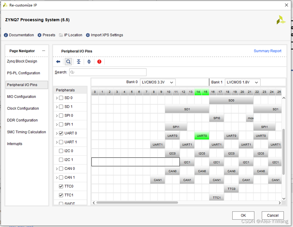
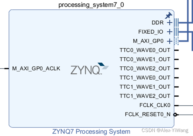
Check TTC0 and TTC1 here, and there will be 6 more Pins in Block Design. (Prepare for the 6 duty cycle PWM output in the next issue~)
Right click on each Pin and set Make External:
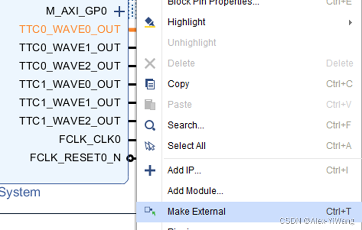
Then bind the output pins in the xdc file.

At the same time, you can see the frequency of the clock in Clock Configuration, where it shows that the clock source of TTC1 and TTC2 is from the internal clock of CPU_1x, and the frequency is 133.333333MHz

At this point, the Block Design part is set up.
After modifying the Block Design first, you need to click F6 to perform the Validate Design operation to verify the correctness of the Block Design.
Then click Generate Output Products to generate the output.

Next click Generate Bitstream on the left to output the bitstream file.
Then click File-Export-Export Hardware to export the hardware information.
Then click File-Lauch SDK to create an empty project. (The process of this step can refer to the embedded development series of ZYNQ series videos of the leader of punctual atoms)
After opening the SDK file corresponding to the Vivado project, we can find some ttc reference files provided on the left:

We only need to pay attention to the header file xttcps.h, which is the header file of the TTC module driver in PS, and gives a more detailed function definition
Also find some example files:

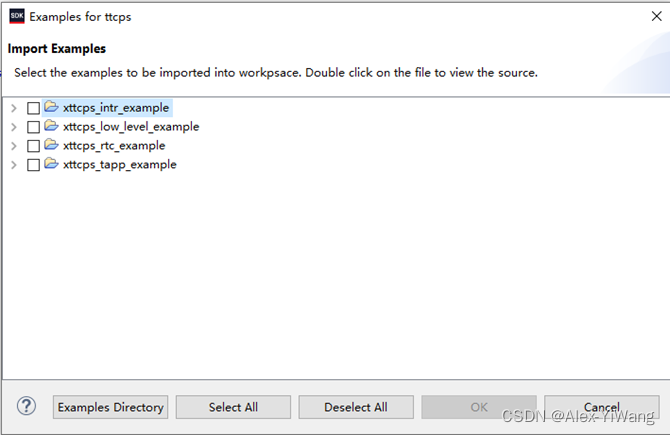
Here we mainly explain the code of the first case.
2.2 Case Analysis
Here, readers need to open the above case file by themselves~ Since no additional hardware settings are required, the above content can be seen directly in the SDK.
Here we briefly introduce the ttc setting process for this file.
This document internally gives a case of using TTC to generate an interrupt, which is divided into several steps.
1. Set up the interrupt system: SetupInterruptSystem()
Line547+552: Initialize the interrupt controller
Line562: Register interrupt handling
Line569: Enable interrupt
2. Set the Ticker timer: SetupTicker()
It should be noted that SetupTicker contains the initialization of information, the setting of a single timer, and the setting of interrupts. It is equivalent to combining these parts together.
The function starts from Line257, which refers to a data structure TmrCntrSetup, defined in Line100
typedef struct {
u32 OutputHz; /* Output frequency */
XInterval Interval; /* Interval value */
u8 Prescaler; /* Prescaler value */
u16 Options; /* Option settings */
} TmrCntrSetup;
And Line261 calls the array defined by Line131:
static TmrCntrSetup SettingsTable[2] = {
{100, 0, 0, 0}, /* Ticker timer counter initial setup, only output freq */
{200, 0, 0, 0}, /* PWM timer counter initial setup, only output freq */
};
It can be seen that this array is used to set the status of Ticker timer and PWM timer respectively, including: output frequency; interval value; prescaler coefficient; output option setting.
The setting of the output option is realized by the OR operation in Line267. The specific optional parameters can be found in the definition in xttcps.h:

Going back to xttcps_intr_example, Line267 defines the current mode as the interval mode, and at the same time sets no waveform output. (If the output waveform is set here, when the counter value is equal to the matching value, the output will be reversed to realize the waveform output).
After that, the SetupTimer function is called in Line275 to realize the specific setting of a single timer. This function is defined in Line469. Note that the transmission of information is realized through TTC_TICK_DEVICE_ID.
The main function is to initialize the device (XTtcPs_LookupConfig, XTtcPs_CfgInitialize), and pass the settings in SetupTicker, including (setting option mode XTtcPs_SetOptions, calculating interval value XTtcPs_CalcIntervalFromFreq, setting interval value XTtcPs_SetInterval, setting prescaler coefficient XTtcPs_SetPrescaler)
After the setting is completed, the set device TtcPsTick is obtained.
Back in SetupTicker, Line285 implements the setting of the interrupt controller, defines the device and the interrupt processing function.
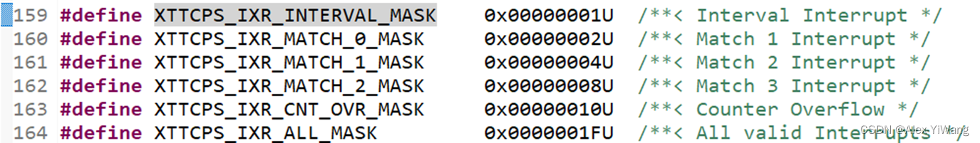
The interrupt handler function TickHandler is defined in Line592, first obtain the interrupt type in Line599, and then clear the interrupt in Line600. Judge the type of interrupt at Line602, here is XTTCPS_IXR_INTERVAL_MASK, its definition and other types of interrupts, we can find it in xttcps_hw.h, which defines six types of interrupts:
When the corresponding type of interruption is detected, we use TickCount to accumulate the number of interval terminal occurrences.
Back in SetupTicker, the interrupt enable operation is performed on Line294 and Line300, and then the timer is set on Line305.
3. Set the PWM timer: SetupPWM()
I believe this is also the part that many people pay more attention to.
Line328 implements some setting information, mainly storing the second element of the previous array.
Line334 sets the interval mode, match mode, and enables the output of wave, which ensures that when the count value is the same as the match value, the output signal will be reversed. Therefore, the interval value can be used to set the PWM period, and the matching value can be used to set the PWM duty cycle.
Line342 also calls SetupTimer to realize the specific setting of a single timer. For details, please refer to the above part. This function is defined in Line469. Note that the transmission of information is realized through TTC_PWM_DEVICE_ID.
The main function is to initialize the device (XTtcPs_LookupConfig, XTtcPs_CfgInitialize), and pass the settings in SetupPWM, including (setting option mode XTtcPs_SetOptions, calculating interval value XTtcPs_CalcIntervalFromFreq, setting interval value XTtcPs_SetInterval, setting prescaler coefficient XTtcPs_SetPrescaler)
After the setting is completed, the set device TtcPsPWM is obtained
Line352 realizes setting of interrupt controller, device ID, interrupt processing function and matching value pointer by calling XScuGic_Connect.
The interrupt processing function PWMHandler is defined in Line637. When the interrupt signal is detected to be an interval interrupt (that is, a cycle is output), it will call XTtcPs_SetMatchValue in Line653 to set the matching value. It is mentioned in the code comment that the matching register 0 is a special Yes, if the output is enabled, the polarity of the output is modified when the match value is equal to the count value.
But the note here is easy to be misunderstood. The functions of the three matching registers of the TTC timer are inconsistent, and not all of them can be used for waveform output. In the official ZYNQ example, register0 is designated as Special, that is, when the counter When it is equal to the matching value of register0, a special interrupt event will be triggered and the output level will be inverted. Experiments have shown that for the same Counter, register1 and register2 will not affect the inversion of PWM output, but since there are three Counters in each TTC, in fact, three values of register0 can be set to achieve three PWMs with different duty ratios. Output.
Back in SetupPWM, the interrupt enable operation is performed on Line361 and Line367, and then the timer is set on Line372.
4. Gradually modify the duty cycle: WaitForDutyCycleFull()
This function is defined in Line397, mainly through the TickHandler function will update PWM_UpdateFlag to TRUE in Line607 after each cycle outputs a PWM wave, and then satisfy the if condition in WaitForDutyCycleFull, thereby modifying the value of the global variable MatchValue. Through Line643 in the interrupt processing function PWMHandler, the assignment of MatchValue to MatchReg is realized, so that the value of MatchReg can be modified in Line653, and then the duty cycle can be modified.
The overall logic only needs to grasp the following three points: 1. Interval mode interrupt: update the flag at the end of the PWM cycle; 2. Modify the duty cycle: detect the flag to modify the global variable and change the duty cycle; 3. PWM output interrupt processing function (also interval mode interrupt) to set the matching value in.
5. Stop the counter: XTtcPs_Stop()
Here, XTtcPs_Stop is directly called on Line236 and Line238 to stop the counter.
This is the whole content of this issue. If you like my article, don't forget to like + bookmark + follow, and share it with your friends~