The I2C and serial ports we usually use are actually serial buses, but because of their low speed and simple timing, they are rarely mentioned in high-speed serial buses. But in today's high-speed era, some high-speed buses, such as LVDS, MIPI, SERDES, SATA, USB, etc., and when we study or study any kind of bus, we must consider the differences between these buses in order to use them later. better application in the process. For example, I got a board, this board is relatively low-level, only common LVDS without MIPI bus, but I need to connect a MIPI camera outside, what should I do at this time? 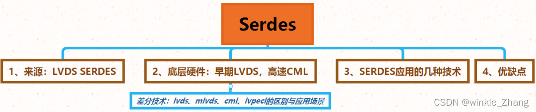
Figure 1 Content block diagram
I am still used to explaining some special buses with a thinking block diagram, so that I can understand a complicated thing from the aspects of history (source), composition and comparison, etc. The following is an in-depth analysis of the SerDes serial bus, because it needs The analysis is simple and in-depth, so I will discard some details, I hope everyone understands.
As a bus, SerDes basically follows the OSI reference model "Example of the Seven-Layer OSI Reference Model", so the analysis of SerDes mainly includes two aspects, one is the physical layer, and the other is the protocol layer. The physical layer is the basis for hardware design and troubleshooting. , The protocol layer is simply the basis of software, FPGA and other designs.
SerDes mainly includes the following parts:
1. The predecessor of SerDes: LVDS SerDes. Among them, LVDS should be familiar to everyone. It will not be expanded here. The main reason is that LVDS is a physical layer for serial interfaces that established standard specifications as "ANSI/TIA/EIA-644" in 1995. The specification lays the foundation for the development of many serial differential buses, and the introduction of LVDS will be the focus of Part 2;
2. SerDes underlying hardware includes early LVDS and current CML:
The LVDS used in the SerDes signal layer operates between 155Mbps and 1.25Gbps, while the CML (current mode signal) operates at 600Mbps and 10+ Gbps.
So now SerDes generally use CML. However, LVDS and CML signals can communicate with each other, but an external resistor is required for level conversion.
Next, the differential technologies such as LVDS and CML will be introduced in detail;
3. The next step is the key point – SerDes technology, explaining several technologies applied by SerDes in detail. This part will not be expanded in detail. There are many excellent materials in this part for reference. I will share the reference materials with you. With the previous foreshadowing, read The documentation isn't too difficult;
4. Finally, summarize the advantages and disadvantages of the SerDes serial bus.
The basic principle of LVDS SerDes understands the characteristics of high speed, long distance and low noise of serial bus.
This part will not be explained in detail, and will be introduced in detail in the next part. Most of the serial buses have the characteristics of high speed, long distance and low noise.
The LVDS used in the SerDes signal layer works between 155Mbps~1.25Gbps, while the CML (current mode signal) works at 600Mbps and 10+ Gbps,
So now SerDes generally use CML. However, LVDS and CML signals can communicate with each other, but an external resistor is required for level conversion.
LVDS has been introduced in detail above. When reading documents, I often see CML and LVPECL. So what is the difference between these differential signals?
Differential technology: the difference and application scenarios of LVDS, MLVDS, CML, and LVPECL
Differential transmission is a signal transmission technology, which is different from the traditional method of one signal line and one ground line. Differential transmission is transmitted on both lines. signal, the two signals have the same amplitude and opposite phases. The signals transmitted on these two lines are differential signals. The signal receiving end compares the difference between these two voltages to judge the logic state sent by the sending end. On the circuit board, differential traces must be two lines of equal length, equal width, close proximity, and on the same level.
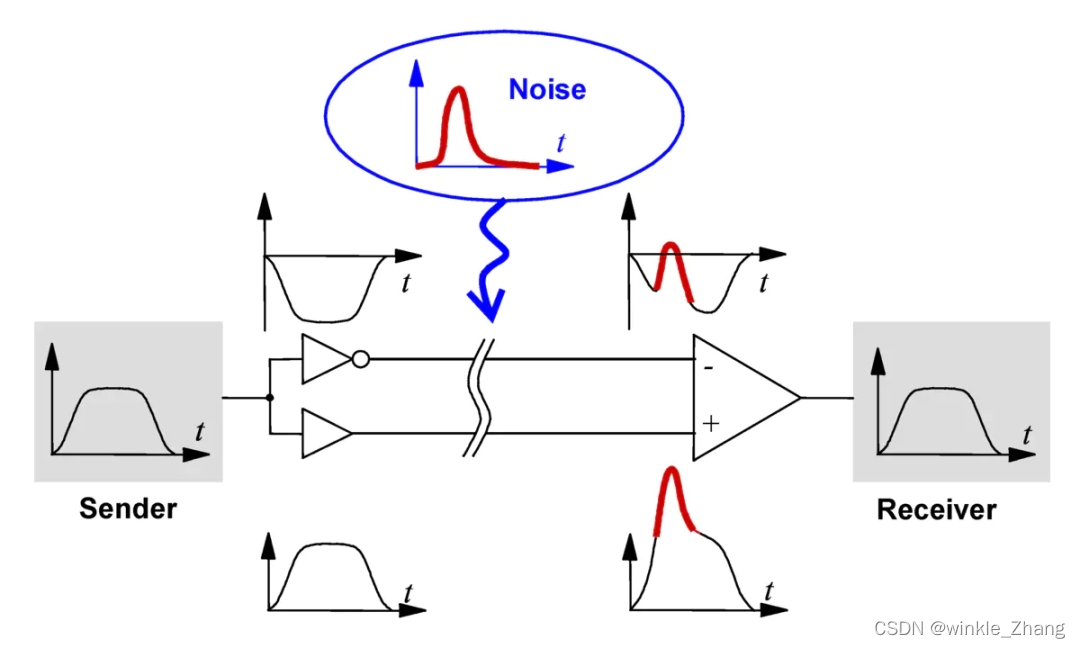
Figure 2 Schematic diagram of differential signal
Compared with the traditional one signal line and one ground line (that is, single-ended signal) routing, the advantages and disadvantages of differential signals are respectively.
advantage:
1. Strong anti-interference ability. Generally, the interference noise will be loaded onto the two signal lines at the same time, and the receiving end only cares about the difference between the two signals, so the external common mode noise can be completely canceled out.
2. Can effectively suppress electromagnetic interference (EMI). Since the two wires are close together and the signal amplitudes are equal, the amplitudes of the coupled electromagnetic fields between the two wires and the ground wire are also equal, and their signal polarities are opposite. According to the right-hand spiral rule, their magnetic force lines are mutually cancelled. The more tightly coupled two wires are, the more magnetic field lines cancel each other out. The less electromagnetic energy is released to the outside world.
3. Timing positioning is accurate. The receiving end of the differential signal is the point where the difference between the signal amplitudes on the two lines changes positively and negatively, which is used as the point where the logic 0/1 transition is judged. Ordinary single-ended signals use the threshold voltage as the transition point of the signal logic 0/1, which is greatly affected by the ratio of the threshold voltage to the signal amplitude voltage, and is not suitable for low-amplitude signals.
4. The current source at the sending end is always on, eliminating the spikes caused by switching noise (required in single-ended technology) and the electromagnetic interference EMI caused by the continuous on-off of high-current transistors.
shortcoming:
If the area of the circuit board is very tight, the single-ended signal can have only one signal line, and the ground line must go to the ground plane, while the differential signal must go to two lines of equal length, equal width, close proximity, and on the same level. This situation often occurs when the pin spacing of the chip is so small that only one trace can pass through it.
Several typical differential signals (refer to the following content: https://www.jianshu.com/p/e36244b0b98c?utm_campaign=maleskine&utm_content=note&utm_medium=seo_notes&utm_source=recommendation)
To achieve high-speed data transmission, there are several differential techniques to choose from. These differential technologies have several common advantages of differential signals, but there are great differences in performance, power consumption and application scenarios. The figure below lists the most commonly used differential signaling technologies and their main parameters.
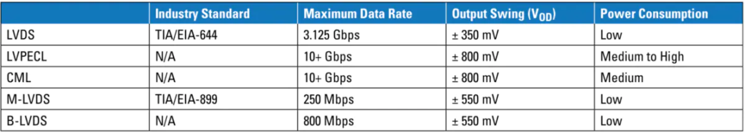
Figure 3 Industry standards for various differential technologies
The LVDS signal swing is low, 350mv, corresponding to very low power consumption, and the rate reaches 3.125Gbps. In general, the advantages of simple termination method, low power consumption and noise make LVDS the first choice for applications ranging from tens of Mbps to 3Gbps or even higher.