Overview
The class android.graphics.PorterDuffXfermodeinherits from android.graphics.Xfermode. When drawing with Canvas in Android, you can use PorterDuffXfermode to mix the pixels of the drawn graphics with the pixels of the corresponding positions in the Canvas according to certain rules to form new pixel values, thereby updating the final pixel color value in the Canvas, This creates a lot of interesting effects. When using PorterDuffXfermode, you need to pass it as a parameter to the Paint.setXfermode(Xfermode xfermode)method, so that when drawing with the brush paint, Android will use the incoming PorterDuffXfermode, if you don't want to use Xfermode, you can execute it Paint.setXfermode(null).
Porter and Duff in the class PorterDuffXfermode are the names of two people who wrote a paper together in 1984 called "Compositing Digital Images" , click to view the paper. We know that a pixel is composed of four components of RGBA. This paper discusses how to realize the mixing between pixels of different digital images. This paper proposes a variety of pixel mixing modes. If you have done image processing development, you will know more about it. This technology is also similar to the Alpha blending technology in OpenGL.
PorterDuffXfermode supports more than a dozen pixel color mixing modes: CLEAR, SRC, DST, SRC_OVER, DST_OVER, SRC_IN, DST_IN, SRC_OUT, DST_OUT, SRC_ATOP, DST_ATOP, XOR, DARKEN, LIGHTEN, MULTIPLY, SCREEN.
We will analyze several code snippets below to study the use and working principle of PorterDuffXfermode.
Example 1
Before we demonstrate how to use PorterDuffXfermode, let's take a look at the following example, the code is as follows:
@Override
    protected void onDraw(Canvas canvas) {
        super.onDraw(canvas);
        //设置背景色
        canvas.drawARGB(255, 139, 197, 186);

        int canvasWidth = canvas.getWidth();
        int r = canvasWidth / 3;
        //绘制黄色的圆形
        paint.setColor(0xFFFFCC44);
        canvas.drawCircle(r, r, r, paint);
        //绘制蓝色的矩形
        paint.setColor(0xFF66AAFF);
        canvas.drawRect(r, r, r * 2.7f, r * 2.7f, paint);
    }
We rewrite the View's onDraw method, first set the View's background color to green, then draw a yellow circle, and then draw a blue rectangle, the effect is as follows:
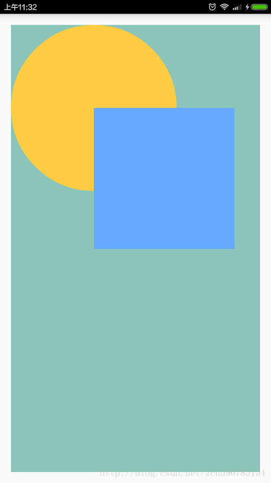
The above demonstration is the normal drawing process of Canvas, without using PorterDuffXfermode. Let's briefly analyze the above code:
First, we call the canvas.drawARGB(255, 139, 197, 186) method to draw the entire Canvas into one color. After executing this code, the ARGB colors of the color values of all pixels on the canvas are (255, 139, 197, 186) , since the alpha component of the pixel is 255 instead of 0, all pixels are opaque at this point.
When we execute canvas.drawCircle(r, r, r, paint), Android will draw a yellow circle with a yellow brush at the position of the drawn circle. At this time, all the pixel color values inside the circle are equal to The ARGB colors are all 0xFFFFCC44, and then the pixels with the color value ARGB of (255, 139, 197, 186) in the corresponding position in the Canvas are replaced with these yellow pixels, so that the yellow circle is drawn on the Canvas.
When we execute canvas.drawRect(r, r, r * 2.7f, r * 2.7f, paint), Android will draw a blue rectangle with a blue brush at the position of the drawn rectangle, at this time the entire rectangle The ARGB color of all internal pixel color values is 0xFF66AAFF, and then these blue pixels are used to replace the corresponding pixels in the same position in the Canvas, so that the pixels in the lower right corner of the yellow circle and some other background color pixels are replaced by blue pixels, which draws the blue rectangle onto the Canvas.
Although the above process is simple, understanding the specific pixel update process when Canvas draws is the basis for truly understanding the working principle of PorterDuffXfermode.
Example 2
Next, we use PorterDuffXfermode to modify the above code. The modified code is as follows:
@Override
protected void onDraw(Canvas canvas) {
super.onDraw(canvas);
//设置背景色
canvas.drawARGB(255, 139, 197, 186);
int canvasWidth = canvas.getWidth();
int r = canvasWidth / 3;
//正常绘制黄色的圆形
paint.setColor(0xFFFFCC44);
canvas.drawCircle(r, r, r, paint);
//使用CLEAR作为PorterDuffXfermode绘制蓝色的矩形
paint.setXfermode(new PorterDuffXfermode(PorterDuff.Mode.CLEAR));
paint.setColor(0xFF66AAFF);
canvas.drawRect(r, r, r * 2.7f, r * 2.7f, paint);
//最后将画笔去除Xfermode
paint.setXfermode(null);
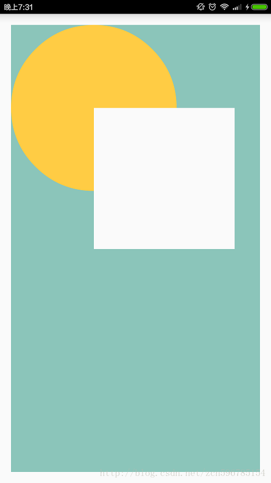
}The effect is as follows:
Let's analyze the above code:
First, we call the canvas.drawARGB(255, 139, 197, 186) method to draw the entire Canvas as a color, and all pixels are opaque at this time.
Then we draw a yellow circle on the Canvas by calling canvas.drawCircle(r, r, r, paint).
Then we execute the code paint.setXfermode(new PorterDuffXfermode(PorterDuff.Mode.CLEAR)) to set the PorterDuff mode of the brush to CLEAR.
Then call the canvas.drawRect(r, r, r * 2.7f, r * 2.7f, paint) method to draw a blue rectangle, but finally a white rectangle appears on the interface.
After painting, we call paint.setXfermode(null) to remove Xfermode from the brush.
Let's analyze the reasons for the appearance of the white rectangle in detail. Generally, when we call the canvas.drawXXX() method, we will pass in a brush Paint object. When drawing, Android will first check whether the brush Paint object has Xfermode set. If Xfermode is not set, then the drawn graphics will be directly covered by the corresponding position of the Canvas. The original pixel; if Xfermode is set, the pixel color of the corresponding position in the Canvas will be updated according to the specific rules of Xfermode. In this example, when the canvas.drawCirce() method is executed, the brush Paint does not set the Xfermode object, so the drawn yellow circle directly covers the pixels on the Canvas. When we call canvas.drawRect() to draw a rectangle, the brush Paint has set the value of Xfermode to PorterDuff.Mode.CLEAR. At this time, Android first draws such a rectangle in memory, and the pixels in the drawn graphic are called the source. Pixel (source, src for short), the pixel within the rectangle at the corresponding position in the Canvas of the drawn rectangle is called the destination pixel (destination, dst for short). The four ARGB components of the source pixel and the four ARGB components of the target pixel at the same position on the Canvas are calculated according to the rules defined by Xfermode to form the final ARGB value, and then the ARGB value of the target pixel is updated with the final ARGB value. The Xfermode in this example is PorterDuff.Mode.CLEAR. This rule is relatively simple and rude. It directly requires all four ARGB components of the target pixel to be set to 0, that is, (0, 0, 0, 0), which is the transparent color, so we pass canvas.drawRect() draws a transparent rectangle on Canvas. Since the background of the Activity's own screen is white, a white rectangle is displayed here.
Example three
We are modifying the code in Example 2 and place the code related to drawing circles and rectangles between canvas.saveLayer() and canvas.restoreToCount(). The code is as follows:
@Override
protected void onDraw(Canvas canvas) {
super.onDraw(canvas);
//设置背景色
canvas.drawARGB(255, 139, 197, 186);
int canvasWidth = canvas.getWidth();
int canvasHeight = canvas.getHeight();
int layerId = canvas.saveLayer(0, 0, canvasWidth, canvasHeight, null, Canvas.ALL_SAVE_FLAG);
int r = canvasWidth / 3;
//正常绘制黄色的圆形
paint.setColor(0xFFFFCC44);
canvas.drawCircle(r, r, r, paint);
//使用CLEAR作为PorterDuffXfermode绘制蓝色的矩形
paint.setXfermode(new PorterDuffXfermode(PorterDuff.Mode.CLEAR));
paint.setColor(0xFF66AAFF);
canvas.drawRect(r, r, r * 2.7f, r * 2.7f, paint);
//最后将画笔去除Xfermode
paint.setXfermode(null);
canvas.restoreToCount(layerId);
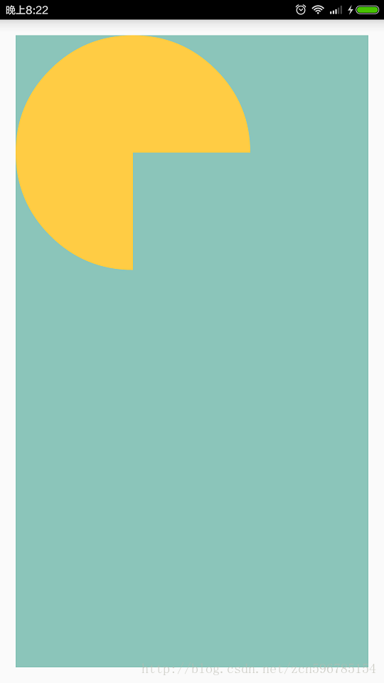
}The effect is as follows:
Let's analyze the above code:
First, we call the canvas.drawARGB(255, 139, 197, 186) method to draw the entire Canvas as a color, and all pixels are opaque at this time.
Then we put the main code between canvas.saveLayer() and canvas.restoreToCount(), and I indented the code a bit. When we write the code between canvas.saveXXX() and canvas.restoreXXX(), it is recommended to indent the code inside. This way of writing is easy to read the code. Of course, whether the code is indented is not mandatory, nor will affect the performance.
The following points need to be explained about the layer in canvas drawing:
Canvas supports layer rendering technology. Canvas has a layer by default. When we usually call various drawXXX() methods of canvas, we actually draw everything on canvas, which is the default layer.
We can also create a new layer through canvas.saveLayer(), and the new layer is placed on top of the default canvas layer. When we execute canvas.saveLayer(), all our drawing operations are drawn to our new layer. Not the default layer of canvas.
The ARGB values of all pixels of the layer generated by the canvas.saveLayer() method are (0, 0, 0, 0), that is, the layer generated by the canvas.saveLayer() method is initially completely transparent.
The canvas.saveLayer() method will return an int value to represent the ID of the layer. After we finish drawing the new layer, we can draw the layer to canvas by calling canvas.restoreToCount(layer) or canvas.restore(). The layer goes up, which completes the drawing of a layer.
Then you may feel strange, we just put the code for drawing circles and rectangles between canvas.saveLayer() and canvas.restoreToCount(), why no longer display white rectangles like in example 2?
When we analyzed the code of the second example, we knew that the target color of the final rectangular area was reset to the transparent color (0,0,0,0), and finally it was only displayed as a white rectangle because the Activity background color was white. In this example, after we finish drawing on the newly created layer, the target color of the rectangular area is actually reset to the transparent color (0, 0, 0, 0), so that the entire new layer is only 3/4 of the circle. Not transparent, the rest of the pixels are transparent, and then we call canvas.restoreToCount() to draw the layer to the Canvas again. When drawing a new layer to the Canvas, Android will use the pixel color on the entire layer to update the color of the pixel at the corresponding position of the Canvas. It is not a simple replacement, but the Canvas and the new layer are Alpha blended, see here link here. Since there are only two types of pixels in our layer: fully transparent and fully opaque, there are no partially transparent pixels, and the four components of the color value of fully transparent pixels are all 0, so in this example, the Canvas and the new layer are used. The rules for doing alpha blending are simplified, specifically:
- If the Alpha component of a pixel on the new layer is 255, that is, the pixel is completely opaque, then Android will directly use the ARGB value of the pixel as the color value of the pixel at the corresponding position of the Canvas.
- If the Alpha component of a pixel on the new layer is 0, that is, the pixel is completely transparent. In this example, the Alpha component of a pixel with an Alpha component of 0, and its RGB components are also 0, then Android will retain the color value of the pixel at the corresponding position of the Canvas. .
In this way, when the new layer is drawn on the Canvas, the pixels in the completely opaque 3/4 yellow circle will completely cover the pixels in the corresponding position of the Canvas, and since the pixels ARGB of the rectangular area drawn on the new layer are all (0,0 ,0,0), so the corresponding rectangular area on the Canvas will keep the previous background color, so that there will be no white rectangle.
In most cases, we want the effect achieved in this example, not the white rectangle formed in example 2, so in most cases when using PorterDuffXfermode, it is combined with canvas.saveLayer(), canvas.restoreToCount() , write the key code between these two methods.
A picture of the gods that has been passed around without a brain
If you Google or Baidu PorterDuffXfermode related blog posts, you will definitely see the following picture, as shown below:
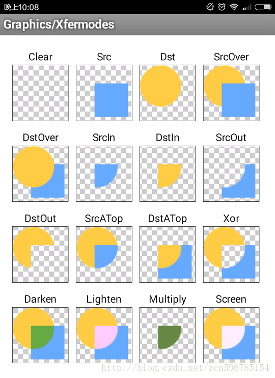
This picture is one of the Demo examples of the API that comes with the Android sdk. The physical path corresponding to the source code is C:\Users\iSpring\AppData\Local\Android\sdk\samples\android-23\legacy\ApiDemos \src\com\example\android\apis\graphics\Xfermodes.java.
This picture demonstrates the effect of drawing a yellow circle first, then setting the brush paint to 16 different PorterDuffXfermodes, and then drawing a blue rectangle.
This picture demonstrates the effect of drawing a yellow circle first, then setting the brush paint to 16 different PorterDuffXfermodes, and then drawing a blue rectangle.
The above effect seems to be normal, but what I want to say is that this wildly circulated image above is very misleading to developers. The starting point of this image is good, and it wants to intuitively express the effects of various PorterDuffXfermode. In order to achieve this purpose, it manipulates the yellow and blue graphics drawn in the code.
The code that creates the yellow circle in its code is as follows:
// create a bitmap with a circle, used for the "dst" image
    static Bitmap makeDst(int w, int h) {
        Bitmap bm = Bitmap.createBitmap(w, h, Bitmap.Config.ARGB_8888);
        Canvas c = new Canvas(bm);
        Paint p = new Paint(Paint.ANTI_ALIAS_FLAG);

        p.setColor(0xFFFFCC44);
        c.drawOval(new RectF(0, 0, w*3/4, h*3/4), p);
        return bm;
    }
The above code first creates a new Bitmap object by specifying the size. Such a Bitmap object defaults to the color of all pixels (0, 0, 0, 0). Since the alpha component of each pixel defaults to 0, the entire Bitmaps are all transparent. Then use the Bitmap to construct a Canvas object, so that when c.drawOval() is executed, the yellow circle will be drawn to the Canvas, and the graphics on the Canvas will be automatically updated to the previously created Bitmap bound to the Canvas. . In this way, there are two kinds of pixels in the Bitmap, one is the pixel located in the circular range, and its pixel value is 0xFFFFCC44, and the other is the pixel located outside the circular range, and its pixel value is 0x00000000, that is, the Bitmap The yellow circular area in is opaque, the rest of the range is transparent. Finally, the Bitmap object is returned, so that the yellow circle can be drawn through canvas.drawBitmap() in the onDraw() method. Everyone pay attention to the RecF parameter in c.drawOval(), right is w*3/4, not w, bottom is h*3/4, not h. What is this indicating? This shows that the actual size of the Bitmap is larger than the yellow circular area you see in the above image, and the two sizes are inconsistent.
The code to create the blue rectangle looks like this:
// create a bitmap with a rect, used for the "src" image
    static Bitmap makeSrc(int w, int h) {
        Bitmap bm = Bitmap.createBitmap(w, h, Bitmap.Config.ARGB_8888);
        Canvas c = new Canvas(bm);
        Paint p = new Paint(Paint.ANTI_ALIAS_FLAG);

        p.setColor(0xFF66AAFF);
        c.drawRect(w/3, h/3, w*19/20, h*19/20, p);
        return bm;
    }
The code to create the blue rectangle is very similar to the code to create the yellow circle. Everyone pay attention to the parameters in c.drawRect(), the value of left is w/3, not 0, the value of top is h/3, not 0, the value of right is w*19/20, not w, The value of bottom is h*19/20, not h. What is this indicating? This means that the actual size of the Bitmap is larger than the blue rectangular area you see in the above image, and the two sizes are inconsistent.
After the above analysis, we know that the actual size of the Bitmap drawn in the API Demo is larger than the actual size we can see with the naked eye, which leads to the result of the above picture that will cause great confusion to developers. Let me give an example. For example, when the value of PorterDuffXfermode is set to CLEAR, the result seen by the naked eye in the API Demo is that the entire circle is invisible. In fact, this is wrong, because if the makeDst(), makeSrc() methods The actual size of the obtained Bitmap is the same as the actual size of the drawn circle and rectangle, so the effect should be that only the lower right corner of the circle where the circle intersects with the rectangle is clipped to be transparent, and the other 3/4 of the circle is It should still be visible; for example, when the value of PorterDuffXfermode is set to SRC, the result seen by the naked eye in the API Demo is that the drawn yellow circle is completely invisible, and the drawn blue rectangle is completely visible. In fact, this is wrong. , because if the actual size of the Bitmap obtained by the makeDst() and makeSrc() methods is the same as the actual size of the drawn circle and rectangle, then the effect should be that the drawn yellow circle is visible, and the drawn blue rectangle is also It can be seen that the area where the circle and the rectangle intersect is blue, that is, the correct effect should be that the blue rectangle covers the yellow circle.
Calculation rules for different blending modes
I modified the code with reference to API Demo, so that the actual size of the Bitmap obtained by the makeDst() and makeSrc() methods is the same as the actual size of the drawn circle and rectangle, and for the convenience of observation and comparison, I set the background of the entire View to green , the final running effect is as follows:
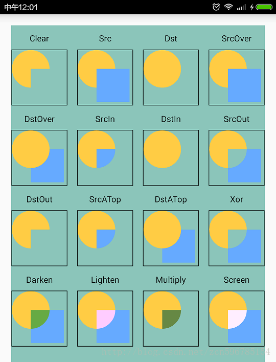
The above example demonstrates the effect of 16 blending modes, and the key code is placed between canvas.saveLayer() and canvas.restoreToCount(). The code is placed on CSDN, which is an Android Studio project, click here to download .
Android defines 18 rules for color mixing of source pixels and target pixels in the class android.graphics.PorterDuff, and briefly introduces the calculation methods of various mixing rules in the form of comments in the code. Please refer to the source code link on GitHub .
We know that the color of a pixel consists of four components, namely ARGB, the first component A represents the Alpha value, and the last three components RGB represent the color. We use S to represent the source pixel, the color value of the source pixel can be expressed as [Sa, Sc], a in Sa is the abbreviation of alpha, Sa represents the alpha value of the source pixel, c in Sc is the abbreviation of color, Sc represents The RGB of the source pixel. We use D to represent the target pixel, the color value of the target pixel can be expressed as [Da, Dc], Da represents the Alpha value of the target pixel, and Dc represents the RGB of the target pixel.
The rules for calculating the color of the source pixel and the destination pixel in different blending modes are as follows:
CLEAR:[0, 0]
SRC [Sa, Sc]
DST : [Da, Dc]
SRC_OVER : [Sa + (1 - Sa)*Da, Rc = Sc + (1 - Sa)*Dc]
DST_OVER : [Sa + (1 - Sa) * Yes, Rc = Dc + (1 - Yes) * Sc]
SRC_IN : [Sa * Da, Sc * Da]
DST_IN : [Sa * Da, Sa * Dc]
SRC_OUT : [Sa * (1 - Da), Sc * (1 - Da)]
DST_OUT [Da * (1 - Sa), Dc * (1 - Sa)]
SRC_ATOP : [Da, Sc * Da + (1 - Sa) * Dc]
DST_ATOP [Sa, Sa * Dc + Sc * (1 - Da)]
XOR : [Sa + Da - 2 * Sa * Da, Sc * (1 - Da) + (1 - Sa) * Dc]
DARKEN : [Sa + Da - Sa * Da, Sc * (1 - Da) + Dc * (1 - Sa) + min (Sc, Dc)]
LIGHTEN : [Sa + Da - Sa * Da, Sc * (1 - Da) + Dc * (1 - Sa) + max (Sc, Dc)]
MULTIPLY Sa [Sa * Da, Sc * Dc]
SCREEN : [Sa + Da - Sa * Da, Sc + Dc - Sc * Dc]
ADD:Saturate(S + D)
OVERLAY:Saturate(S + D)
In this article, we take CLEAR as an example to introduce the working principle of PorterDuffXfermode in detail. The working principle of other blending modes is the same, except that the color mixing calculation rules of the source pixel and the target pixel are different. You can verify the effect diagram of the above 16 rules according to the calculation rules of various modes.
Finally, it needs to be explained that several mixing rules such as DARKEN, LIGHTEN, OVERLAY do not work under GPU hardware acceleration. If you feel that the mixing mode is not used correctly, you can call the View.setLayerType(View.LAYER_TYPE_SOFTWARE, null) method to put our View disables GPU hardware acceleration and switches to software rendering mode, so that all blending modes can be used normally. For details, please refer to the blog post "GPU hardware acceleration control in Android and its limitations in 2D graphics rendering" .
Finally, to sum up, PorterDuffXfermode is used to achieve color mixing between the newly drawn pixels and the existing pixels in the corresponding position on the Canvas according to the mixing rules.
I hope this article will help you to correctly understand how PorterDuffXfermode works!
This article is transferred from: http://blog.csdn.net/iispring/article/details/50472485