Article Directory
In order to realize the motion trajectory planning of the robotic arm, and at the same time to learn more about the theory of robotics and apply it to time, I use Robotic ToolBox to build a four-axis robot model and realize motion control simulation, and record and share it.
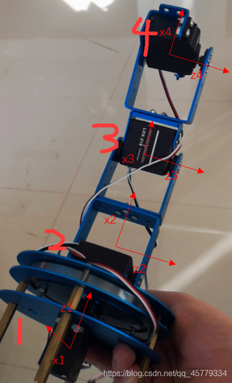
Physical four-axis robotic arm

Robotic ToolBox Robotic Arm Modeling
1. Create a DH table for the robotic arm
Here I choose standard DH parameters for modeling, and the meaning of each parameter is shown in the figure: What
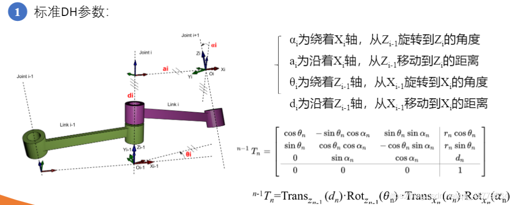
needs to be noted is:
- When determining the axis, the Z-axis is the rotation axis of the connecting rod joint (here, the rotation axis of the steering gear), and the X-axis is the common vertical of the Z-axis of the current joint and the Z-axis of the next joint (going up one by one) Line (here is the parallel line of the robot arm lever).
Establish a robotic arm coordinate system
Coordinate system establishment method:

The robot arm coordinate system establishment is shown in the figure:
Establish DH table according to coordinate system
The first thing that needs to be done is to create a DH table for the robotic arm :
| i | theta | d (unit: m) | a (unit: m) | alpha |
|---|---|---|---|---|
| 1 | 0 | 0 | 0 | pi/2 (z1 rotates 90° around x1 to z2) |
| 2 | 0 | 0 | 0.105 | 0 |
| 3 | 0 | 0 | 0.09 | 0 |
| 4 | 0 | 0 | 0.04 | 0 |
2. Code modeling
%% 机械臂建模
% 定义各个连杆以及关节类型,默认为转动关节
% theta d a alpha
L1=Link([ 0 0 0 pi/2 ], 'standard'); % [四个DH参数], options
L2=Link([ 0 0 0.105 0], 'standard');
L3=Link([ 0 0 0.09 0], 'standard');
L4=Link([ 0 0 0.04 0], 'standard');
robot=SerialLink([L1,L2,L3,L4]); % 将四个连杆组成机械臂
robot.name='4DOF Robotic Arm';
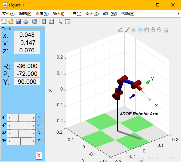
robot.display();
view(3); % 解决robot.teach()和plot的索引超出报错
robot.teach();
robot.plot([0 pi/2 0 0]);
Kinematics simulation of robotic arm
1. Positive kinematics simulation
Given the rotation angle of each joint, the robot can realize motion control.
clc;
clear;
%% 机械臂建模
% 定义各个连杆以及关节类型,默认为转动关节
%          theta      d       a      alpha
L1=Link([     0       0        0      pi/2], 'standard'); % [四个DH参数], options
L2=Link([     0       0      0.105     0], 'standard');
L3=Link([     0       0      0.09      0], 'standard');
L4=Link([     0       0      0.04      0], 'standard');
b=isrevolute(L1);
robot=SerialLink([L1,L2,L3,L4],'name','Irvingao Arm'); % 将四个连杆组成机械臂
robot.name='4DOF Robotic Arm';
robot.display();

%% 轨迹规划
% 初始值及目标值
init_ang=[0 0 0 0];
targ_ang=[0, -pi/6, -pi/5, pi/6];
step=200;

[q,qd,qdd]=jtraj(init_ang,targ_ang,step); %关节空间规划轨迹,得到机器人末端运动的[位置,速度,加速度]
T0=robot.fkine(init_ang); % 正运动学解算
Tf=robot.fkine(targ_ang);
subplot(2,4,3); i=1:4; plot(q(:,i)); title("位置"); grid on;
subplot(2,4,4); i=1:4; plot(qd(:,i)); title("速度"); grid on;
subplot(2,4,7); i=1:4; plot(qdd(:,i)); title("加速度"); grid on;

Tc=ctraj(T0,Tf,step); % 笛卡尔空间规划轨迹,得到机器人末端运动的变换矩阵
Tjtraj=transl(Tc);
subplot(2,4,8); plot2(Tjtraj, 'r');
title('p1到p2直线轨迹'); grid on;
subplot(2,4,[1,2,5,6]);
plot3(Tjtraj(:,1),Tjtraj(:,2),Tjtraj(:,3),"b"); grid on;
hold on;
view(3); % 解决robot.teach()和plot的索引超出报错
qq=robot.ikine(Tc, 'q0',[0 0 0 0], 'mask',[1 1 1 1 0 0]); % 逆解算
robot.plot(qq);
The motion effects of the robotic arm are as follows:
2. Inverse kinematics simulation
Here we define the coordinates of the target point for our convenience, so we change the unit of a to m.
%% 机械臂建模
% 定义各个连杆以及关节类型,默认为转动关节
%          theta      d       a      alpha
L1=Link([     0       0        0      pi/2], 'standard'); % [四个DH参数], options
L2=Link([     0       0      10.5     0], 'standard');
L3=Link([     0       0      9      0], 'standard');
L4=Link([     0       0      4      0], 'standard');

b=isrevolute(L1);
robot=SerialLink([L1,L2,L3,L4],'name','Irvingao Arm'); % 将四个连杆组成机械臂
robot.name='4DOF Robotic Arm';
robot.display();
view(3);
robot.teach();
robot.plot([0 pi/2 0 0]);
Reference article:
- Robotic arm robot-(4) Robotics Toolbox robot simulation
- Error resolution 1: MATLAB robot toolbox RVC error: Number of robot DOF must be >= the same number of 1s in the mask matrix
- Error resolution 2: Matlab robot toolbox inverse solution error Number of robot DOF must be >= the same number of 1s in the mask matrix