Original address of this article: https://blog.csdn.net/tainjau/article/details/87338803
Article Directory
-
- Write in front
- 1. Data frame
- 2. Command frame
-
- 2.1, route request command (Route Request)
- 2.2. Route reply command (Route reply)
- 2.3. Network Status Command (Network Status)
- 2.4. Disconnect command (Leave)
- 2.5, route record command (Route Record)
- 2.6, rejoin request command (Rejoin Request)
- 2.7, rejoin request command (Rejoin response)
- 2.8, link status commands
- 2.9. Network report command (Network report)
- 2.10, network update command (Network update)
Write in front
- When I first joined the company last year, I learned about zigbee for a while and wrote the fourth chapter of the study notes (part 1) . Later, because of the busy business (and I was lazy), I didn’t update the blog anymore. It's so depraved, so I have to re-write my blog recently. ps: This article was written last year. I have been lying in You Daoyun's notes. I will update it today.
- As mentioned in the previous chapter , the frame difference of the NWK layer is controlled by the first two bits of the frame control field (Frame Control) of the frame header, while the format of the data frame and the command frame are different. The difference is as shown in the figure below.
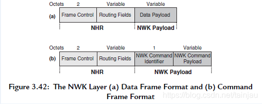
1. Data frame
- The network layer header field of the data frame is composed of a control field and a routing field obtained by proper combination according to needs. The information carried by the payload of the data frame is the data of the future application layer. ps: In the future, the read attributes and write attributes of the application layer are data at the aps layer, which are all sent out using data frames.
2. Command frame
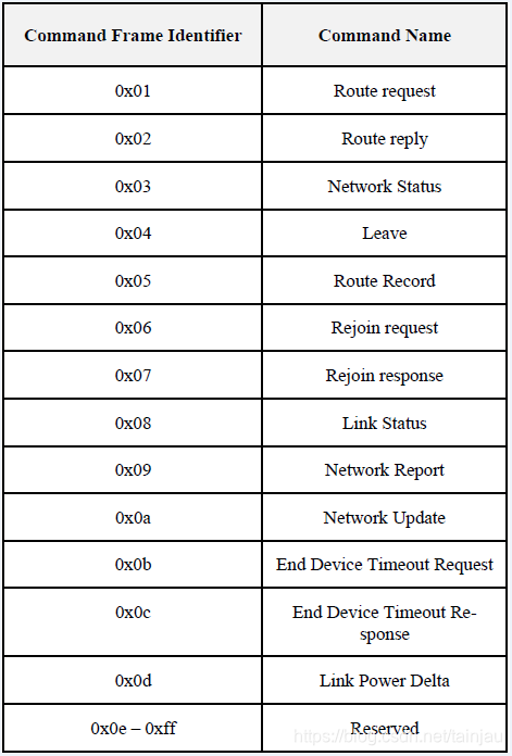
- The difference of the command frame is determined by the command frame identifier (NWK Command Identifier) in the NWK payload. This field is composed of one byte.
2.1, route request command (Route Request)
- The device uses the route request command to request other devices within its wireless communication range to find a route to the destination device, so as to establish a stable route in the network that enables information to reach the destination device faster and more economically. The payload format of the route request command is shown in the figure below.
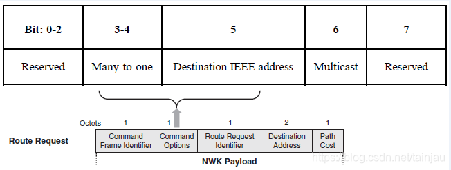
2.1.1, Command Options
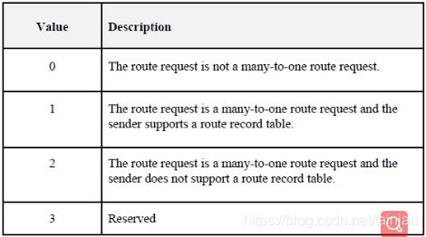
2.1.1.1. Many-to-one routing (Many-to-one)
ps: For more specific knowledge about many-to-one, you can refer to this document: https://www.silabs.com/community/wireless/zigbee-and-thread/knowledge-base.entry.html/2017/12 /18/_many-to-one_source-JRvm
0: indicates that the many-to-one mechanism is not applicable, that is, unicast route discovery.
1: Indicates that the many-to-on mechanism is enabled. In the entire network, the central node will periodically send out many-to-one (default 60s, broadcast), so that all devices with routing capabilities in the entire network receive this command Frame, and parse out the path to the central node.
2.1.1.2.Destination IEEE address
2.1.1.3. Multicast subdomain (Mulicast)
- The multicast subdomain is 1 bit. Only when the command frame requests multicast group routing, its value is 1. In this case, the destination address field contains the Group ID of the desired group.
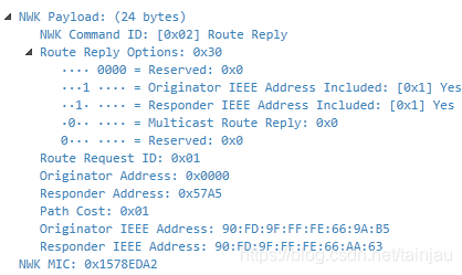
2.2. Route reply command (Route reply)
- The destination device of the route reply command uses the route reply command to notify the source device of the route request that the request command has been received. The following figure shows the load format of the state route response command established by the router through which the ZigBee route request can make the frame more quickly routed from the source address to the destination address.
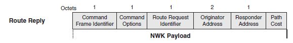
- ps: When the A routing device in the zigbee network needs to know the path to the B device, it can initiate a route discovery to the B device (without many-to-one). After the B device receives it, it will use the route as the route Reply back.
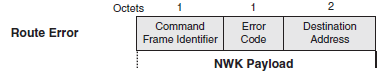
2.3. Network Status Command (Network Status)
- The device uses network status commands to report errors and other conditions from the NWK layer of a specific device to the peer NWK layer entities of other devices in the network. NWK status commands can also be used to diagnose network problems, such as address conflicts.
- Of course, there are also articles on the Internet that call it a routing error command. When the device cannot forward data, it uses the routing error command. This command informs the source device that sends the data frame that an error occurred while transmitting the data frame.
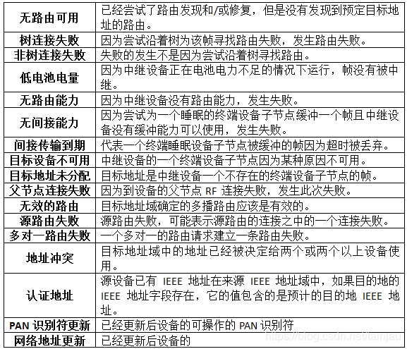
- The following is the Error Code corresponding to the network status command: The
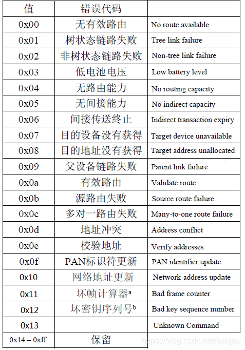
detailed description is as follows:
2.4. Disconnect command (Leave)
- The network layer management entity uses a disconnect command to notify other devices in the network that the device is leaving the network or request a device to leave the network (that is, the device is off the network). The frame format is as follows:
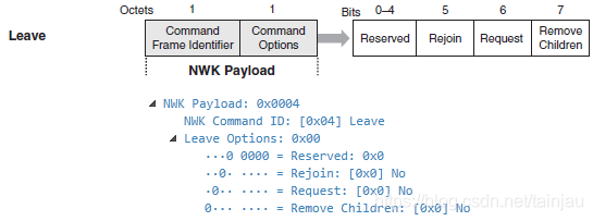
2.4.1, Rejoin the subdomain (Rejoin)
- The re-connected subfield is 1 bit in the position of bit 5. If the value of this subdomain is 1, the device that is disconnected from its current parent device reconnects to the network (rejoin). If the value of this subdomain is 0, the device will not reconnect to the network.
2.4.2, request subdomain (Request)
- The length of the requested subfield is 1bit in the bit6 position. If the value of this bit is 1, then the disconnect command frame requests another device to leave the network. If the subfield value is 0, then the disconnect command frame indicates that the sending device is ready to disconnect from the network.
2.4.3, Disconnect the sub-device subdomain (Remove Children)
- The sub-field of the disconnected sub-device is the position of 1bit in bit7. If the value of this bit is 1, then the child device of the device also leaves the network (leave).
2.5, route record command (Route Record)
- The route record command allows the route taken by a unicast packet to pass through the network to be recorded in the command payload and sent to the target device. The route record usually sends the route record to the central node after the routing device has a path to the central node before the first data sent, so that the central node has a path to the routing device (the central node’s source routing table is established)
- The load of the routing record command must be arranged in the format shown in the figure below.
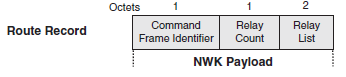
2.5.1, Response Counter Domain (Relay Count)
- Contains the number of replies to the reply list field of the routing record command. The initiating device initializes it to 0, and adds 1 every time it receives a response.
2.5.2, Response List Domain (Relay List)
- The reply list field is a list of 2-byte short addresses of nodes that reply to the data packet. Address is the least meaningful format. Before sending a data packet, the receiving nodes append their short addresses to the list.
2.6, rejoin request command (Rejoin Request)
- The reconnect request command allows the device to reconnect to its network. This is usually done in response to a communication failure, for example when the terminal device cannot communicate with its originating parent device.
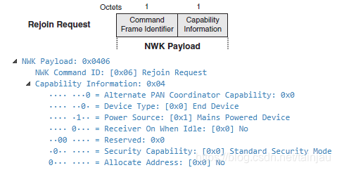
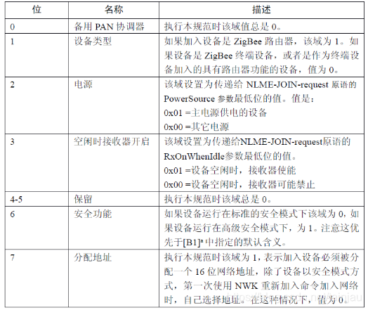
- The capability information information is as follows:
2.7, rejoin request command (Rejoin response)
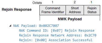
- The device sends a reconnection response command to notify its child devices of the short address and the reconnection status. The frame format is as follows
2.7.1. Short Address
- If the reconnection is successful, then this 2-byte field contains the short address of a new designated reconnection device. If the reconnection is unsuccessful, this field contains the broadcast address (0xffff).
2.7.2, Rejoin Status (Rejoin Status)
- 0x00: indicates that the rejoin request is successful
2.8, link status commands
- The connection status command frame allows communication between neighboring routers until their input link cost to each other.
- This is what we often say about neighbor table related information. By default, in the entire network, the link status is sent every 16s to maintain the neighbor table between devices.
2.8.1, connection status command selection domain (command option)
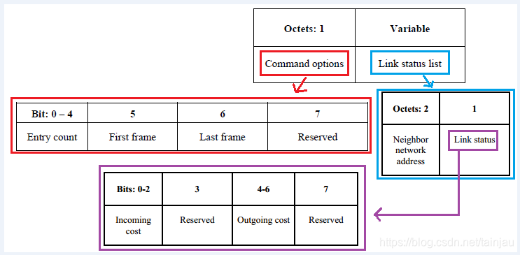
- The number of entries subfield of the command option field indicates the number of link state entries in the link state table. If this is the first frame of the sender's link state, the first frame subfield is set to 1, and if this is the last frame of the sender's link state, the last frame subfield is set to 1. If the sender's link status happens to be one frame, both the first and last frame bits should be set to 1.
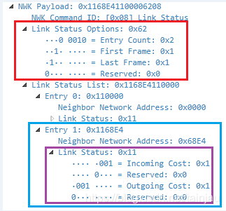
- As shown in the figure above, the number of entry count is 2, so the link status list has two pieces of information.
2.8.2, link state table domain
- The link state entries are sorted in increasing order by network address. If all router neighbors do not fit in one frame, multiple frames should be sent. When sending multiple frames, the last network address of the link state list of frame N is equal to the first network address of the link state list of frame N+1.
Each link state entry contains the network address of a router neighbor, the lowest byte first, and the link state byte second. The input consumption field contains the neighbor's link consumption estimated by the device, which is a value between 1 and 7. The output consumption domain includes the value of the output consumption domain from the neighbor table.
2.9. Network report command (Network report)
- The network layer report command allows the device to report network events to the coordinator. The events that can be reported are wireless communication channel conditions and PAN ID conflicts. The network layer report command payload format is shown in the figure below.
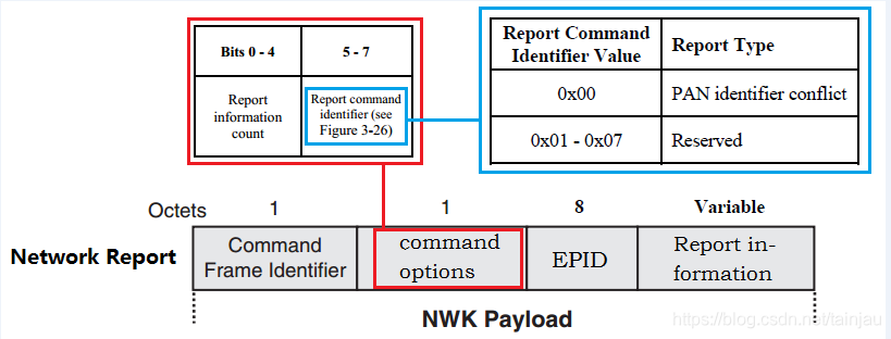
2.9.1. Command options
- The command selection area contains the report information count subdomain and the report command identifier (Report command identifier)
2.9.2, EPID domain
- The EPID field contains a 64-bit EPID to identify which network member the reporting device is
2.10, network update command (Network update)
- The network update command allows the device determined by the nwkManagerAddr parameter in the NIB to broadcast configuration information changes to all devices in the network. For example, the broadcast network will change the short PAN identifier.
The rest have not been encountered yet, and will be updated if they are encountered.
Article Directory
-
- Write in front
- 1. Data frame
- 2. Command frame
-
- 2.1, route request command (Route Request)
- 2.2. Route reply command (Route reply)
- 2.3. Network Status Command (Network Status)
- 2.4. Disconnect command (Leave)
- 2.5, route record command (Route Record)
- 2.6, rejoin request command (Rejoin Request)
- 2.7, rejoin request command (Rejoin response)
- 2.8, link status commands
- 2.9. Network report command (Network report)
- 2.10, network update command (Network update)
Write in front
- When I first joined the company last year, I learned about zigbee for a while and wrote the fourth chapter of the study notes (part 1) . Later, because of the busy business (and I was lazy), I didn’t update the blog anymore. It's so depraved, so I have to re-write my blog recently. ps: This article was written last year. I have been lying in You Daoyun's notes. I will update it today.
- As mentioned in the previous chapter , the frame difference of the NWK layer is controlled by the first two bits of the frame control field (Frame Control) of the frame header, while the format of the data frame and the command frame are different. The difference is as shown in the figure below.
1. Data frame
- The network layer header field of the data frame is composed of a control field and a routing field obtained by proper combination according to needs. The information carried by the payload of the data frame is the data of the future application layer. ps: In the future, the read attributes and write attributes of the application layer are data at the aps layer, which are all sent out using data frames.
2. Command frame
- The difference of the command frame is determined by the command frame identifier (NWK Command Identifier) in the NWK payload. This field is composed of one byte.
2.1, route request command (Route Request)
- The device uses the route request command to request other devices within its wireless communication range to find a route to the destination device, so as to establish a stable route in the network that enables information to reach the destination device faster and more economically. The payload format of the route request command is shown in the figure below.
2.1.1, Command Options
2.1.1.1. Many-to-one routing (Many-to-one)
ps: For more specific knowledge about many-to-one, you can refer to this document: https://www.silabs.com/community/wireless/zigbee-and-thread/knowledge-base.entry.html/2017/12 /18/_many-to-one_source-JRvm
0: indicates that the many-to-one mechanism is not applicable, that is, unicast route discovery.
1: Indicates that the many-to-on mechanism is enabled. In the entire network, the central node will periodically send out many-to-one (default 60s, broadcast), so that all devices with routing capabilities in the entire network receive this command Frame, and parse out the path to the central node.
2.1.1.2.Destination IEEE address
2.1.1.3. Multicast subdomain (Mulicast)
- The multicast subdomain is 1 bit. Only when the command frame requests multicast group routing, its value is 1. In this case, the destination address field contains the Group ID of the desired group.
2.2. Route reply command (Route reply)
- The destination device of the route reply command uses the route reply command to notify the source device of the route request that the request command has been received. The following figure shows the load format of the state route response command established by the router through which the ZigBee route request can make the frame more quickly routed from the source address to the destination address.
- ps: When the A routing device in the zigbee network needs to know the path to the B device, it can initiate a route discovery to the B device (without many-to-one). After the B device receives it, it will use the route as the route Reply back.
2.3. Network Status Command (Network Status)
- The device uses network status commands to report errors and other conditions from the NWK layer of a specific device to the peer NWK layer entities of other devices in the network. NWK status commands can also be used to diagnose network problems, such as address conflicts.
- Of course, there are also articles on the Internet that call it a routing error command. When the device cannot forward data, it uses the routing error command. This command informs the source device that sends the data frame that an error occurred while transmitting the data frame.
- The following is the Error Code corresponding to the network status command: The
detailed description is as follows:
2.4. Disconnect command (Leave)
- The network layer management entity uses a disconnect command to notify other devices in the network that the device is leaving the network or request a device to leave the network (that is, the device is off the network). The frame format is as follows:
2.4.1, Rejoin the subdomain (Rejoin)
- The re-connected subfield is 1 bit in the position of bit 5. If the value of this subdomain is 1, the device that is disconnected from its current parent device reconnects to the network (rejoin). If the value of this subdomain is 0, the device will not reconnect to the network.
2.4.2, request subdomain (Request)
- The length of the requested subfield is 1bit in the bit6 position. If the value of this bit is 1, then the disconnect command frame requests another device to leave the network. If the subfield value is 0, then the disconnect command frame indicates that the sending device is ready to disconnect from the network.
2.4.3, Disconnect the sub-device subdomain (Remove Children)
- The sub-field of the disconnected sub-device is the position of 1bit in bit7. If the value of this bit is 1, then the child device of the device also leaves the network (leave).
2.5, route record command (Route Record)
- The route record command allows the route taken by a unicast packet to pass through the network to be recorded in the command payload and sent to the target device. The route record usually sends the route record to the central node after the routing device has a path to the central node before the first data sent, so that the central node has a path to the routing device (the central node’s source routing table is established)
- The load of the routing record command must be arranged in the format shown in the figure below.
2.5.1, Response Counter Domain (Relay Count)
- Contains the number of replies to the reply list field of the routing record command. The initiating device initializes it to 0, and adds 1 every time it receives a response.
2.5.2, Response List Domain (Relay List)
- The reply list field is a list of 2-byte short addresses of nodes that reply to the data packet. Address is the least meaningful format. Before sending a data packet, the receiving nodes append their short addresses to the list.
2.6, rejoin request command (Rejoin Request)
- The reconnect request command allows the device to reconnect to its network. This is usually done in response to a communication failure, for example when the terminal device cannot communicate with its originating parent device.
- The capability information information is as follows:
2.7, rejoin request command (Rejoin response)
- The device sends a reconnection response command to notify its child devices of the short address and the reconnection status. The frame format is as follows
2.7.1. Short Address
- If the reconnection is successful, then this 2-byte field contains the short address of a new designated reconnection device. If the reconnection is unsuccessful, this field contains the broadcast address (0xffff).
2.7.2, Rejoin Status (Rejoin Status)
- 0x00: indicates that the rejoin request is successful
2.8, link status commands
- The connection status command frame allows communication between neighboring routers until their input link cost to each other.
- This is what we often say about neighbor table related information. By default, in the entire network, the link status is sent every 16s to maintain the neighbor table between devices.
2.8.1, connection status command selection domain (command option)
- The number of entries subfield of the command option field indicates the number of link state entries in the link state table. If this is the first frame of the sender's link state, the first frame subfield is set to 1, and if this is the last frame of the sender's link state, the last frame subfield is set to 1. If the sender's link status happens to be one frame, both the first and last frame bits should be set to 1.
- As shown in the figure above, the number of entry count is 2, so the link status list has two pieces of information.
2.8.2, link state table domain
- The link state entries are sorted in increasing order by network address. If all router neighbors do not fit in one frame, multiple frames should be sent. When sending multiple frames, the last network address of the link state list of frame N is equal to the first network address of the link state list of frame N+1.
Each link state entry contains the network address of a router neighbor, the lowest byte first, and the link state byte second. The input consumption field contains the neighbor's link consumption estimated by the device, which is a value between 1 and 7. The output consumption domain includes the value of the output consumption domain from the neighbor table.
2.9. Network report command (Network report)
- The network layer report command allows the device to report network events to the coordinator. The events that can be reported are wireless communication channel conditions and PAN ID conflicts. The network layer report command payload format is shown in the figure below.
2.9.1. Command options
- The command selection area contains the report information count subdomain and the report command identifier (Report command identifier)
2.9.2, EPID domain
- The EPID field contains a 64-bit EPID to identify which network member the reporting device is
2.10, network update command (Network update)
- The network update command allows the device determined by the nwkManagerAddr parameter in the NIB to broadcast configuration information changes to all devices in the network. For example, the broadcast network will change the short PAN identifier.
The rest have not been encountered yet, and will be updated if they are encountered.