Article Directory
1. Introduction to the drive module
The motor drive module generally uses L298N as the main control chip.
As shown in the figure,
when the 5V power supply of the single-chip microcomputer is used to drive a 5V small motor, the 12V and 5V of the drive module are both connected to the 5V of the single-chip microcomputer (this can be moved, but The speed of the wheel is not fast, please check the connection method below in detail) GND must be connected to the GND of the single-chip microcomputer, that is, it must share the ground with the single-chip microcomputer.
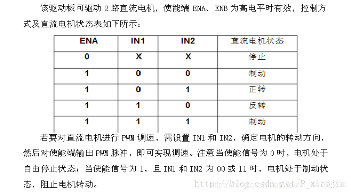
The 6 pin headers in the first row can be connected to the IO port of the single-chip microcomputer. Among them, IN1 to IN4 are the motor logic inputs, which control the forward and reverse rotation. Take the left motor as an example. When IN1=0, IN2=1, it is forward rotation. When IN1=1, IN2=0, it is reverse. Standby is all 0s, and brakes are all 1s. ENA and ENB are the enabling of the two motors. When you need to adjust the speed, unplug the two enabling jumpers directly, and then connect a PWM signal to the first entry. (PWM speed can refer to another article of mine)
2. Wiring method of drive module
1) The first method (not recommended)
Both the 12V power supply port and the 5V power supply port are connected to the 5V voltage
ps of the microcontroller : The first method has a small increase in voltage, and the wheel speed is insufficient, and it may not be possible to adjust the speed
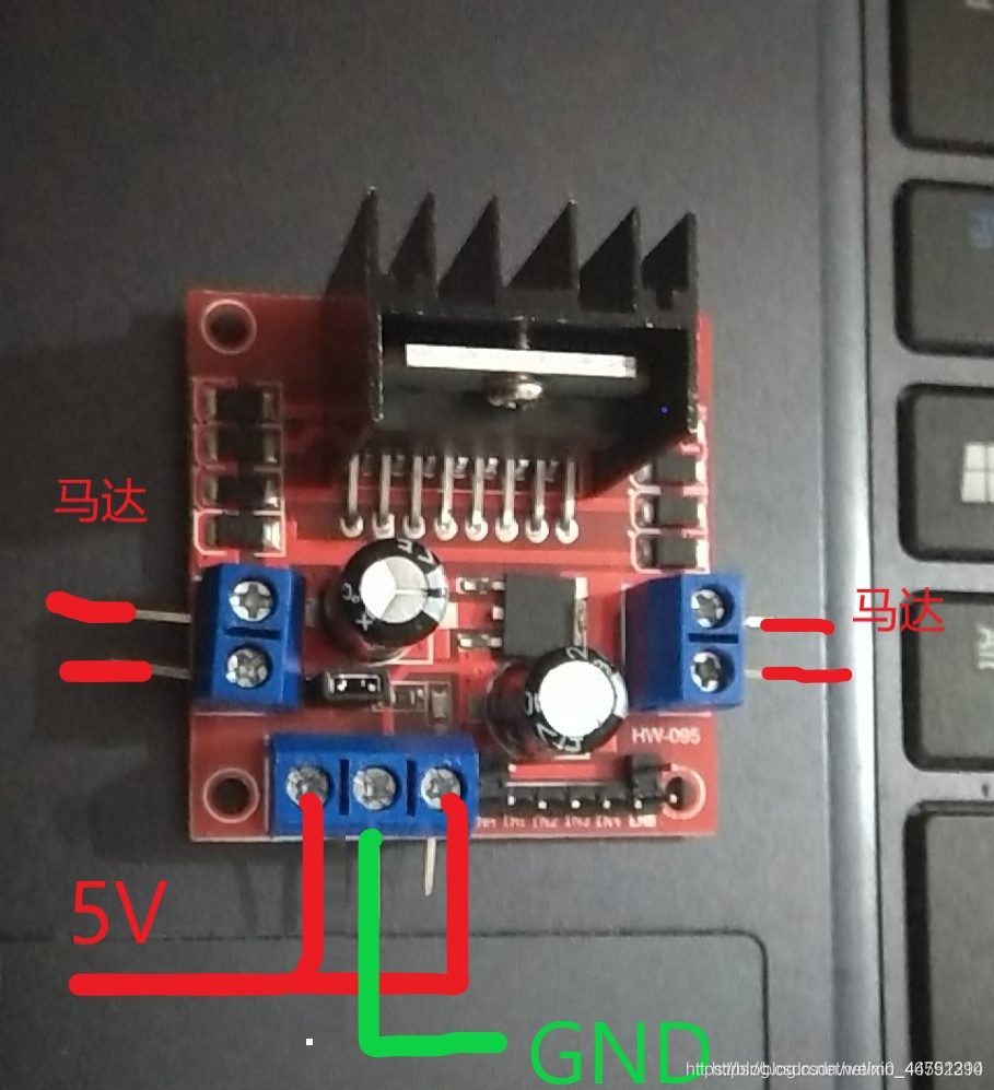
2) The second method (recommended)
When the voltage of 7~12V is connected, the positive 5V does not need to be connected to the voltage, and it can output a voltage of 5V for the single-chip microcomputer. The middle one is connected to the GND of the microcontroller.

ps: Since the 5v power supply port can output 5v voltage, it can be used directly to power the microcontroller
3) The third method (not recommended)
When the input voltage is greater than 12V and less than 24V, you need to unplug the jumper cap next to the power supply. The 5V terminal needs to be connected to a 5V voltage, and GND is still connected to GND.

ps: The input voltage of the third method is relatively large, and I am afraid of affecting the microcontroller when PWM speed is adjusted, so I use the second method
3. How to use the drive module
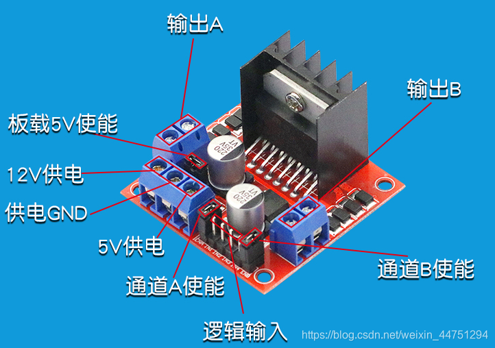
- Instructions:
Output A: Channel A output, connected to the motor
Output B: Channel B output, connected to the motor
12V power supply: Main power supply positive input
Power supply GND: Main power supply positive and negative polarity input
5V output: 5v voltage output terminal, can be used to power the MCU
ENA: Channel A enable, pwm signal connection (for speed control)
ENB: Channel B enable pwm signal connection (for speed control)
IN1~IN4: Logic input IN1~IN2 control channel A, logic input IN3~IN4 control channel B
onboard 5V jumper cap: the onboard 5V output is valid after connecting
4. Reference code
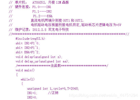
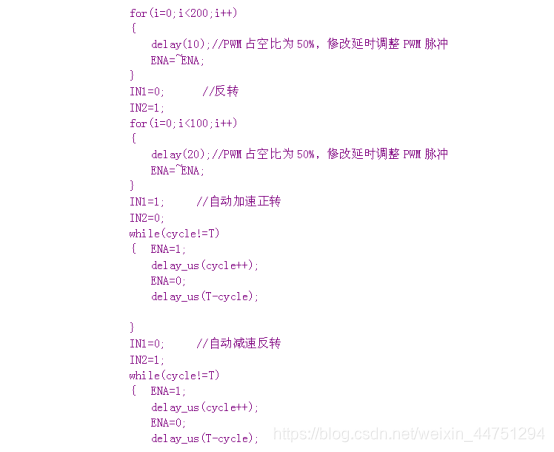
1) 52 single-chip microcomputer version (provided by Taobao, comments can be made if a word document is needed)

2) stm8 version (self-written)
// 关于电机驱动的宏定义
#define RightIN1 PH_ODR_ODR0    //定义为输出量
#define RightIN2 PH_ODR_ODR1
#define LeftIN1  PH_ODR_ODR2     //定义为输出量
#define LeftIN2  PH_ODR_ODR3

void Motor_Init(void)
{
   //设置Ph0-3端口为推挽低速输出
  PH_DDR_DDR0 = 1;
  PH_CR1_C10 = 1;
  PH_CR2_C20 = 0;

  PH_DDR_DDR1 = 1;
  PH_CR1_C11 = 1;
  PH_CR2_C21 = 0;

  PH_DDR_DDR2 = 1;
  PH_CR1_C12 = 1;
  PH_CR2_C22 = 0;

  PH_DDR_DDR3 = 1;
  PH_CR1_C13 = 1;
  PH_CR2_C23 = 0;


}

//小车左转
void Motor_TurnLeft(void)
{
    RightIN1 = 0;
    RightIN2 = 1;

    LeftIN1 = 1;
    LeftIN2 = 1;
  //  delay_ms(2000);
}


//小车右转
void Motor_TurnRight(void)
{
    RightIN1 = 1;
    RightIN2 = 1;

    LeftIN1 = 1;
    LeftIN2 = 0;
  //  delay_ms(2000);
}


//小车直走
void Motor_GoForward(void)
{

    RightIN1 = 0;
    RightIN2 = 1;

    LeftIN1 = 1;
    LeftIN2 = 0;
  //  delay_ms(2000);
}


//小车倒退
void Motor_GetBack(void)
{
    RightIN1 = 1;
    RightIN2 = 0;

    LeftIN1 = 0;
    LeftIN2 = 1;
  //  delay_ms(2000);
}


void Motor_BeParking(void)
{
    RightIN1 = 1;
    RightIN2 = 1;

    LeftIN1 = 1;
    LeftIN2 = 1;
}
5. Common problems
1) The motor won't rotate?
(1) There is a noise but the gear does not rotate, it may be that the voltage is not enough, increase the voltage
(2) There is an error in the wiring, and it is not shared with the MCU, etc.
(3) The logic terminal is programmed incorrectly, and the correct enable
2) Do you want to unplug the jumper caps on ENA and ENB?
If you just need to rotate the motor, you don’t need to unplug it. If you need to debug, you need to unplug and then directly connect a PWM signal.
Reference link:
L298N drive motor and single-chip circuit connection diagram
Connection and use of L298N module (stm32 drive and 51 drive)