table of Contents
Morphological operation
Morphological operation itself is the content of image processing to be studied, and computer vision must realize related functions and also realize image processing. In image processing technology, some operations will change the morphology of the image, and these operations are generally called morphological operations.
Talk more professionally:
Image morphology operation is a collection of a series of image processing operations based on shape, mainly based on morphological mathematics based on set theory.
Classification of morphological operations
Two basic operations:
- (1) Expansion : Similar to the convolution operation, suppose there are image A and structure element B, structure element B moves on A, where B defines its center as the anchor point, and calculates the maximum pixel value of A under the coverage of B to replace the anchor The pixel of the dot, where B as the structure body, can be of any shape.
- (2) Corrosion : Corrosion is similar to the expansion operation, the only difference is that the minimum value replaces the pixel value of the image under the anchor point overlap.
Operations based on basic operations:
(1) Open operation : firstly corrode and then expand, small objects can be removed.
(2) Closing operation : first expand and then corrode, and small objects can be filled.
(3) Morphological gradient : expansion minus corrosion.
(4) Top hat : The top hat is the difference image between the original image and the open operation image.
(5) Black hat : The black hat is the difference image between the closed operation image and the original image.
kernel generation API
In morphology, because it involves regional pixel operations, we have to design a kernel to operate on pixels within the kernel. So we need to create a core, here, we use a new API:
getStructuringElement()
Mat getStructuringElement(
    int shape,
    Size ksize,
    Point anchor = Point(-1,-1)
    );
(1) Int type shape, element shape, can be one of cv::MorphShapes.
(2) The ksize of the Size type, the size of the structured element.
(3) Point type anchor, the default value (-1, -1), means that the anchor is positioned at the center. Note that only the shape of the cross-shaped element depends on the anchor position. In other cases, the anchor merely adjusts the amount of movement resulting from the morphological operation.
Mainly talk about the first parameter, there are mainly the following options
(1) MORPH_RECT : rectangular structure area.
(2) MORPH_CROSS , cross-shaped structure area.
(3) MORPH_ELLIPSE , ellipse structure area, filled ellipse inscribed in rectangle Rect (0, 0, esize.width, 0. esize.height).
Swell
principle
Dilation is to calculate the maximum pixel value of A under the coverage of B to replace the pixels of the anchor point .
We need to use the maximum pixel value to replace the pixel of the anchor point, that is, replace the value of the anchor point in the area with the maximum value of the pixel in the area. The so-called anchor point is the center point of the area.
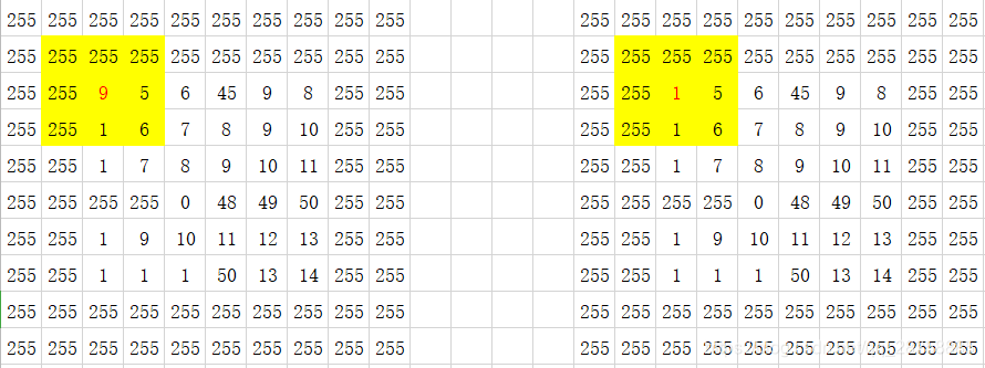
We consider the simplest area, a 3×3 square area. The anchor point is the center point of the square area. Suppose we have the one-dimensional pixel array in the figure below.
For the yellow area in the figure, since the maximum value is 255, the anchor point (red number) changes from 9 to 255.
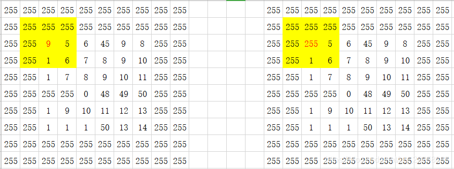
When all the operations are done, the generated image is as follows:
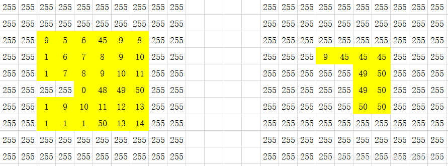
Note: The expansion of the image is based on the original image
If you inflate one point and do the next point after replacing the value, then the entire graph will be 255
That is,
this point is expanded based on 9 in the original image, instead of expanded at the upper left corner of 255 after expansion,
so the anchor point position is 9 instead of 255.
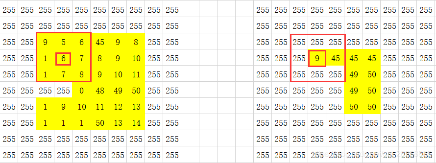
Another example is in "Digital Image Processing (Gonzalez)",
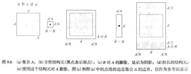
the anchor point of the operator is used to draw a circle along the border of the image, and the place where the operator sweeps is the place where the image expands.
Looking back at our picture, the

operator sweeps across the border of the image, the picture on the right is shown after expansion
Dilation is to replace the small circle of surrounding pixels with a large circle, that is, the white becomes more and the black becomes less.
API
void dilate(
    InputArray src,
    OutputArray dst,
    InputArray kernel,
    Point anchor = Point(-1,-1),
    int iterations = 1,
    int borderType = BORDER_CONSTANT,
    const Scalar& borderValue = morphologyDefaultBorderValue()
);
(1) src of InputArray type, input image. The number of channels can be arbitrary, but the depth should be one of CV_8U, CV_16U, CV_16S, CV_32F or CV_64F. .
(2) The dst of the OutputArray type, that is, the target image, has the same size and type as the input image.
(3) The kernel of InputArray type is used to expand the structure element; if elemenat=Mat(), 3 x
3 rectangular structure element is used . You can use getStructuringElement to create the kernel.(4) Point type anchor: anchor position in the element; the default value (-1, -1) means anchor in the center of the element. .
(5) Iterations of int type: the number of times that the expansion is applied. .
(6) BorderType of int type: pixel extrapolation method, see cv::BorderTypes.
(7) BorderValue of Scalar type: the border value when the border is constant.
Generally speaking, we only need to set the first three parameters, and the latter parameters can be defaulted.
Code
#include<opencv2\opencv.hpp>
#include<iostream>

using namespace std;
using namespace cv;

int main()
{


	Mat src, dst;
	src = imread("ur own path of pic ");
	if (!src.data)
	{


		cout << "could not load image !";
		return -1;
	}

	imshow("src", src);

	Mat kernel = getStructuringElement(MORPH_RECT, Size(7, 7), Point(-1, -1));
	//算子的大小可以根据需要进行调整
	dilate(src, dst, kernel);
	imshow("dilate-src", dst);

	waitKey(0);
	return 0;
}
effect
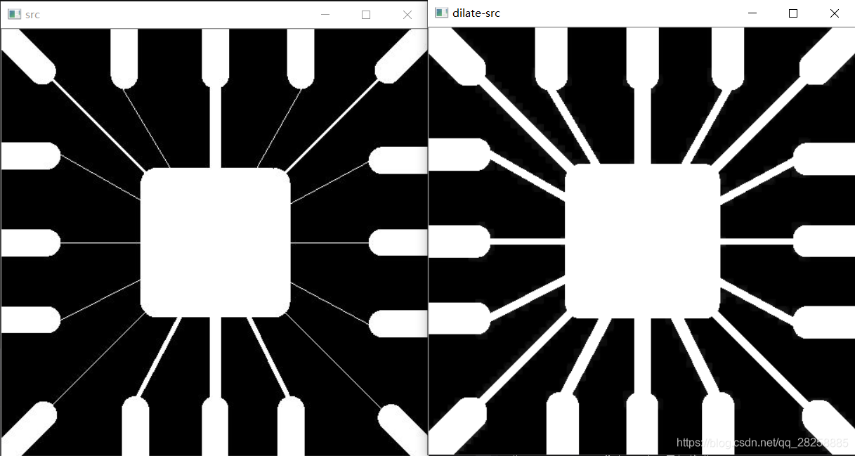
You can see that the thin lines are obviously thicker
corrosion
principle
Corrosion is to calculate the minimum pixel value of A under the coverage of B to replace the pixels of the anchor point .
We need to use the minimum pixel value to replace the pixel of the anchor point, that is, replace the value of the anchor point in the area with the minimum value of the pixel in the area. The so-called anchor point is the center point of the area.
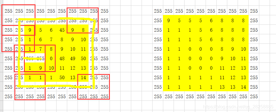
We consider the simplest area, a 3×3 square area. The anchor point is the center point of the square area. Suppose we have the one-dimensional pixel array in the figure below.
For the yellow area in the figure, since the maximum value is 1, the anchor point (red number) changes from 9 to 1.
The generated image is as follows
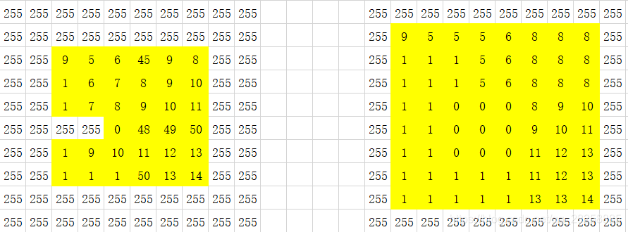
Note: The corrosion of the image is based on the original image
If one point is corroded and the next point is replaced after the value is replaced, then the whole picture is 1
Another example is "Digital Image Processing (Gonzalez)",
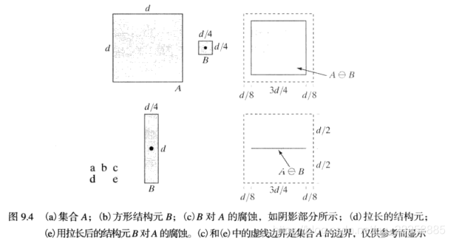
the anchor point of the operator sweeps along the image, and the remaining area is the image after corrosion
Let’s go back to our picture.
Corrosion is to replace the larger circle of surrounding pixels with a smaller circle, that is, the white becomes less and black becomes more.
API
void erode(
    InputArray src,
    OutputArray dst,
    InputArray kernel,
    Point anchor = Point(-1,-1),
    int iterations = 1,
    int borderType = BORDER_CONSTANT,
    const Scalar& borderValue = morphologyDefaultBorderValue()
);
(1) src of InputArray type, input image. This function processes the channels independently and can process pictures of any number of channels, but it should be noted that the depth of the picture to be processed should be one of CV_8U,
CV_16U, CV_16S, CV_32F and CV_64F.(2) The dst of the OutputArray type, that is, the target image, has the same size and type as the input image.
(3) Int type d, the diameter of each pixel neighborhood used in the filtering process. If it is not positive, it is calculated from sigmaSpace.
(4) sigmaColor of double type
, filter sigma in the color space. The larger the parameter value, it means that more colors in the pixel neighborhood (see sigmaSpace) will be mixed together, resulting in a larger semi-isochromatic area.(5) Double type sigmaSpace, filter sigma in the coordinate space. The larger the parameter value, it means that pixels farther away will affect each other, as long as their colors are close enough (see sigmaColor). When d is greater than 0, it specifies the size of the neighborhood regardless of sigmaSpace. Otherwise, d is proportional to sigmaSpace.
(6) The borderType of int type is used to extrapolate the border mode of pixels outside the image. For details, see cv::BorderTypes.
Code
#include<opencv2\opencv.hpp>
#include<iostream>

using namespace std;
using namespace cv;

int main()
{


	Mat src, dst;
	src = imread("path");
	if (!src.data)
	{


		cout << "could not load image !";
		return -1;
	}

	imshow("src", src);

	Mat kernel = getStructuringElement(MORPH_RECT, Size(3, 3), Point(-1, -1));

	erode(src, dst, kernel);
	imshow("erode-src", dst);


	waitKey(0);
	return 0;
}
effect
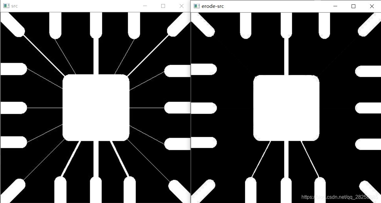
Obviously, the thin thread is corroded