related articles
"[SDIO] Index of articles related to SDIO, SD card, FatFs file system"
1. SD card operation mode
SD card system(Including the host and SD card) defines two modes of operation: the card identification mode and data transfer mode . After the system is reset, the host is in card recognition mode, looking for available SDIO devices on the bus; at the same time, the SD card is also in card recognition mode until it is recognized by the host, that is, when the SD card receives the SEND_RCA (CMD3) command, the SD card It will enter the data transmission mode, and the host will also enter the data transmission mode after all the cards on the bus are identified . In each operation mode, the SD card has several states. As shown in the figure below, the card state can be switched through command control.
| Operation mode | SD card status |
| Inactive mode (Inactive) | Inactive State |
| Card identification mode | Idle State |
| Ready State | |
| Identification State | |
| Data transfer mode | Stand-by State |
| Transfer State | |
| Sending-data State | |
| Receive-data State | |
| Programming State | |
| Disconnect State |
2. SD card recognition mode
When in the card recognition mode, the host resets all the cards in the card recognition mode, verifies the operating voltage range, recognizes the cards and asks what they have issued Relative Card Address(RCA). This operation is performed separately on the CMD command line of each card. In the card recognition mode, all data communication uses only the CMD command line.
On the SD cardRecognition processIn, SD clock frequency works in the range of 100KHz ~ 400KHz .
2.1 SD card Reset
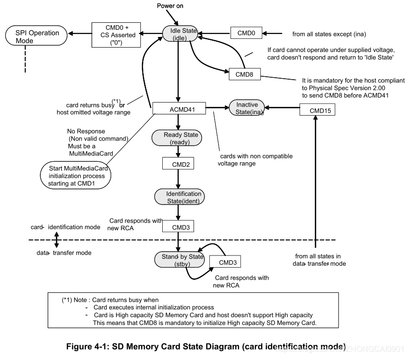
The command GO_IDLE_STATE (CMD0) is a software reset command, no matter what state the current card is in, it will set each card to the Idle state. Cards in the Inactive state are not affected by this command. After the host is powered on, all cards are in the Idle state, including the cards that were previously in the Inactive state.
CMD0After power-on or , the CMD data lines of all cards are in input mode, waiting to receive the next command. These cards are initialized to a default SD card relative address ( RCA=0x0000), and set the SD card driver level register ( DSR) to default to the lowest speed and highest drive capability.
2.2 Confirmation of SD card operating conditions
When the host and the SD card start to communicate, the host may not know the voltage supported by the SD card, and the SD card may not know whether it supports the voltage currently provided. The host sends a reset command ( CMD0), and assumes that its voltage may be supported by the SD card. In order to verify the voltage, the following new commands ( ) are defined in the "Physical Layer Specification Version 2.00" document CMD8.
SEND_IF_COND( CMD8) Used to verify the operating conditions of the SD card interface. SD card by analyzing the CMD8effectiveness of the detected operating condition parameter, the host analyzes CMD8the response to check the validity of the operating conditions. The supplied voltage is specified CMD8by the parameter VHS field of the command. The SD card uses the voltage specified in VHS as the current provided voltage. byCRCwithCheck Pattern('10101010b') to check the validity of the communication between the host and the SD card.
- If the SD card supports operation on the provided voltage, the provided voltage and Check Pattern ('10101010b') will be included in the response command parameters .
- If the SD card does not support working at the provided voltage, it will return without any response and remain in the Idle state. To initialize the large-capacity SD memory card, it must be
ACMD41sent before the first oneCMD8(see Figure 4-1 below). The receivingCMD8can be recognized by the SD card, and the host needs to support "Physical Layer Specification Version 2.00" and the SD card to support this new function.
SD_SEND_OP_COND( ACMD41) Is designed to provide a mechanism for the host to identify and reject cards that do not match the V DD range provided by the host . If the SD card cannot transmit data within the specified range, it should abandon the bus operation and enter the Inactive state. The OCR register defines the relevant voltage level.
Note: It
ACMD41is an application-specific command, so APP_CMD (CMD55) should always be sent before ACMD41. The RCA used for CMD55 in idle_state will be the default value of the SD card (RCA = 0x0000).
By setting it to 0 in ACMD41the parameter of the command ,OCRHostYou can query each card and determineCommon voltage range, And then send the out of range card to the Inactive state. ACMD41Just sent out as a query, the SD card will not start to initialize. After that, the host can select a working voltage, and in this case resend ACMD41 to send the incompatible card to the Inactive state. During the initialization process, the host is not allowed to change the operating voltage range.
2.3 SD card initialization and recognition process
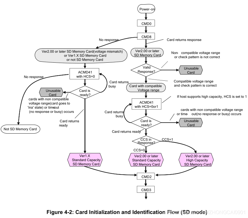
After the bus is activated, the host starts the initialization and identification process of the SD card (refer to Figure 4-2 below). From the initialization process SD_SEND_OP_COND( ) ACMD41starts by setting the operating conditions, and OCR( Operation Conditions Register) in HCS( Host Capacity Support) bits.
The HCS (Host Capacity Support) bit is set to:
- 1: Indicates that the host supports large-capacity SD memory cards .
- 0: Indicates that the host does not support large-capacity SD memory cards .
Use the CMD8expanded ACMD41function of the command; the ACMD41parameter HCS will be sent when the command is sent , and the ACMD41correspondingresponseTo R3 (the OCR Register) , comprising: V DD voltage range , the SD card capacity state of CCS (the Status Card Capacity) . If the SD card does not have a corresponding CMD8, the ACMD41 parameter HCS will be ignored by the SD card. However, if the card does not return a response to CMD8, the host should set HCS to 0 . Standard capacity SD cards will ignore HCS . If HCS is set to 0 , the large-capacity SD card will never return to the ready state (keep the Busy Bit as 0). The Busy Bit in OCR is used by the SD card to inform the host whether the initialization of ACMD41 is complete.
The Busy Bit in OCR is set to:
- 0: Indicates that the SD card is still in the initialization state .
- 1: Indicates that the SD card initialization has been completed .
The host repeatedly sends out ACMD41 until the Busy Bit is set to 1 .SD cardOnly check the Operational Conditions and HCS bits in the OCR at the first ACMD41 . When repeating ACMD41, the host shall not issue other commands except CMD0.
When the card responds to CMD8, the response of ACMD41 contains CCS field information. When the SD card returns to Ready ( Busy Bit is set to 1), CCS takes effect.
CCS (Card Capacity Status) is set to:
- 0: Indicates that the card is Standard Capacity SD Memory Card
- 1: Indicates that the card is High Capacity SD Memory Card
The host performs the same initialization sequence for all new cards in the system, and incompatible cards will be sent to the Inactive state. Then the host sends a command ALL_SEND_CID(CMD2) to each card to obtain its unique card identification (CID) number. The unrecognized card (that is, the card in the ready state) sends its CID number as a response (on the CMD line). After the card sends the CID, it enters the recognition state. Then, the host sends CMD3 (SEND_RELATIVE_ADDR) to request the card to issue a new relative card address (RCA), which is shorter than the CID and will be used to address the card in future data transmission modes. Once the RCA is received, the SD card state will change to the standby state . At this time, if the host wants to assign another RCA number, it can request the card to issue a new number by sending another CMD3 command to the card. The last RCA released is the actual RCA number of the SD card.
3. SD card data transfer mode
Before the end of the SD card recognition mode , the host should maintain the f OD (400kHz) frequency, because during the SD card recognition mode , some SD cards may have operating frequency restrictions. In the data transfer mode , the host can operate the card in the f PP (25MHz) frequency range. The host sends SEND_CSD(CMD9) to obtain data related to the SD card (CSD register), such as block length, card storage capacity, etc.
The broadcast command SET_DSR(CMD4) configures the Driver Stage Register of all identification cards . It is programmed according to the layout (length) of the application bus , the number of cards on the bus, and the frequency of data transmissionDSR register. The clock rate is also switched from f OD to f PP . SET_DSRThe command is an option (not necessary) for the SD card and the host .
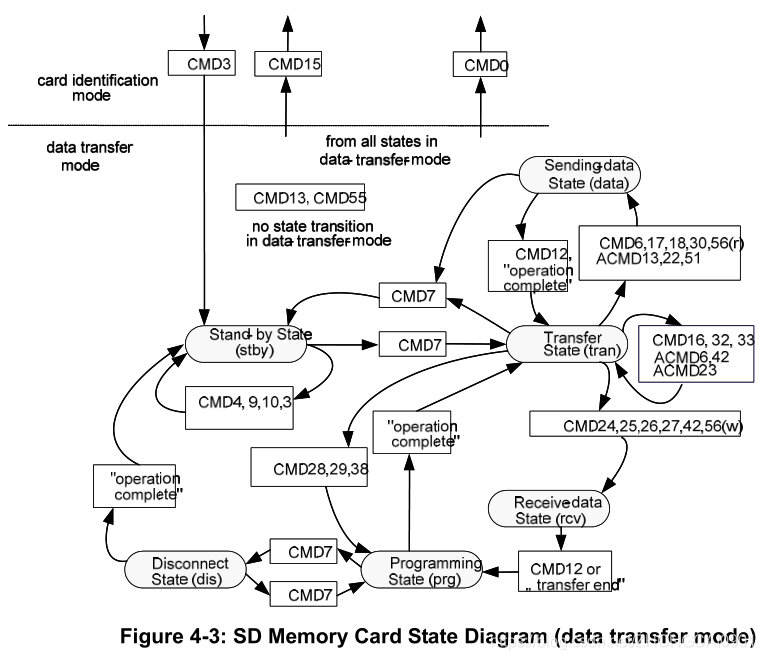
CMD7 used to select an SD card and place it in the transmission state , at the same time there can be only one card is in the transmission state . If the previously selected card is in the transmission state , its connection with the host will be released and it will return to the Stand-by state. When CMD7 is sent with the reserved relative card address "0x0000", all cards are returned to the Stand-by state.
Note: The host reserves RCA = 0x0000 for exit selection.
This can be used before the new card is recognized, without resetting other registered cards. After the SD card in this state has an RCA, it will not respond to identification commands (for example: ACMD41, CMD2).
Note: If the confirmed SD card obtains an RCA that does not match CMD7, the card will be deselected.
The following summarizes the relationship between various data transmission modes:
- All data read commands can be aborted at any time by the stop command (CMD12). The data transfer will be terminated and the SD card will return to the Transfer state. Read commands include: block read (CMD17), multi-block read (CMD18), send write protection (CMD30), send scr (ACMD51) and general commands for read mode (CMD56).
- All data write commands can be aborted at any time by the stop command (CMD12). Before CMD7 cancels the selection of the card, it should stop writing commands. Write commands include: block write (CMD24 and CMD25), program CSD (CMD27), lock/unlock command (CMD42) and regular command in write mode (CMD56).
- Once the data transfer is complete, the SD card will exit the data writing state and move to the Programming state (Successfully transmitted) Or Transfer status (Transmission failed)。
- If a block write operation is stopped and the block length and CRC of the last block are valid, the data will be programmed.
- The SD card can provide buffering for block writes. This means that while the previous block is programmed, the next block can be sent to the SD card. If all write buffers are full, as long as the SD card is in the Programming state (see the SD card state diagram in Figure 4-3), the DAT0 line will remain low (BUSY) .
- There are no buffering options for write CSD, write protection, and erase. This means that when the SD card is busy processing any of these commands, other data transmission commands will not be accepted. As long as the card is busy and in the Programming state, the DAT0 line will remain low .
- When the card is in programming, the parameter setting command is not allowed. Parameter setting commands include: set block length (CMD16), erase block start (CMD32) and erase block end (CMD33).
- When the card is programming, it is not allowed to read commands.
- Moving another card from the Stand-by state to the Transfer state (using CMD7) will not terminate the erase and program operations. The card will switch to the Disconnect state and the DAT line will be released.
- In the Disconnect state, you can use CMD7 to reselect the card. In this case, the card will transition to the Programming state and reactivate the busy indication.
- Resetting the SD card (using CMD0 or CMD15) will terminate any pending or ongoing programming operations. This may destroy the data content on the card. It is the responsibility of the host to prevent this from happening.
- CMD34-37, CMD50, CMD57 are reserved for SD command system expansion. The state transitions of these commands are defined in each command system specification.
4. References
The information referenced by SDIO is as follows: The
download address is as follows:
https://download.csdn.net/download/ZHONGCAI0901/14975835