Take RK3328 as an example to introduce the application of device tree in GPIO.
The pin diagram is as follows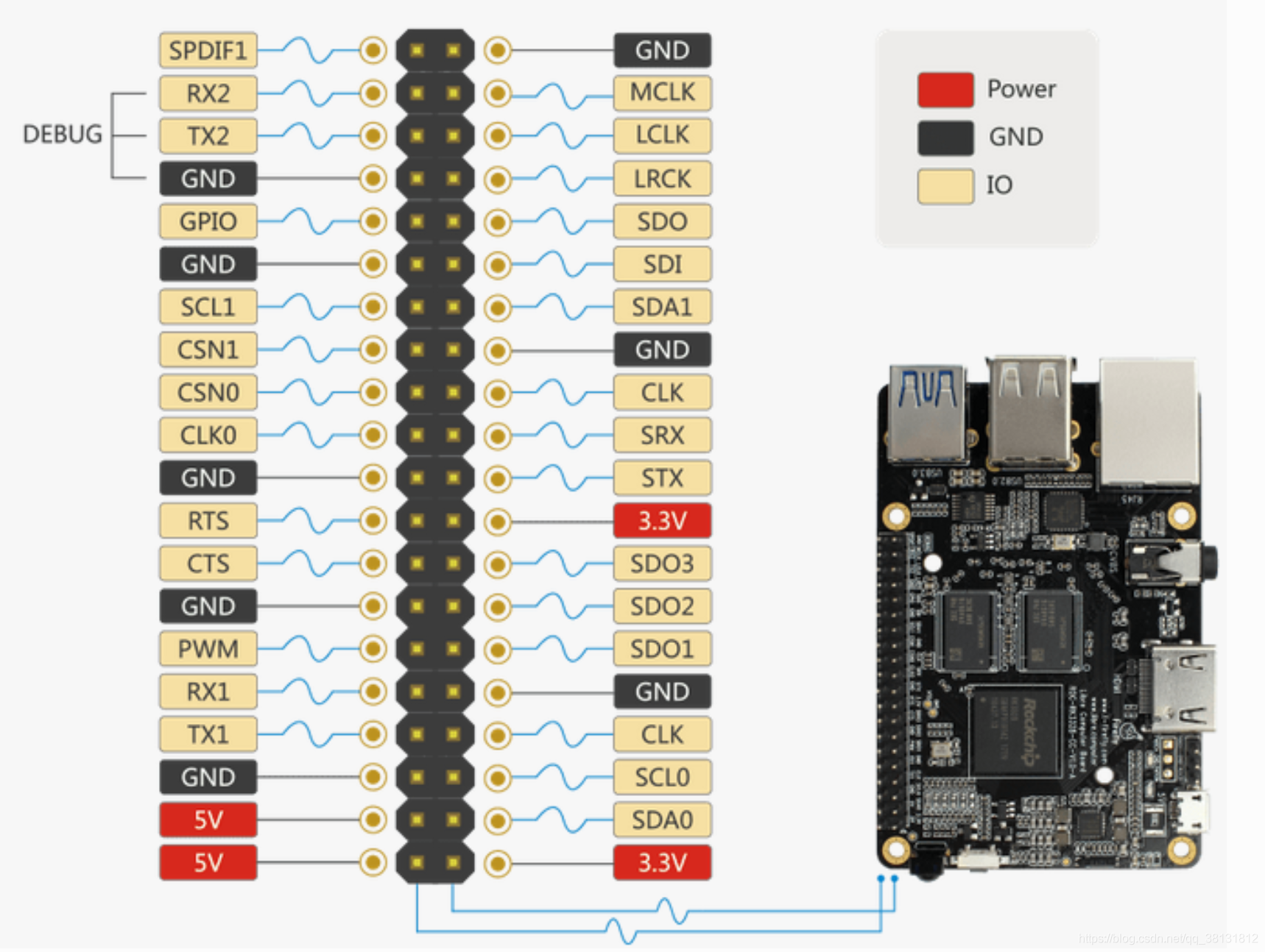
1. First, add GPIO resource description in DTS file:
gpio_demo: gpio_demo {
	            status = "okay";
	            compatible = "rk3328,gpio_demo";
	            firefly-gpio = <&gpio0 12 GPIO_ACTIVE_HIGH>;          /* GPIO0_B4 */
	            firefly-irq-gpio = <&gpio2 29 IRQ_TYPE_EDGE_RISING>;  /* GPIO2_D5 */
	            };
- GPIO_ACTIVE_HIGH: The pin status is always high
- IRQ_TYPE_EDGE_RISING: rising edge trigger
- RK series GPIO is divided into GPIO0, GPIO1, GPIO2... and other groups, each group of GPIO is divided into groups such as A, B, C, D, and each A has 0-7 pins, B, C, D are the same as A . So A=0, B and A differ by 8 pins, C and B differ by 8 pins, and so on. . .
GPIO0_B4Belongs to group B, the base is 8, plus 4 is the pin serial number 12.
Two, add analysis in the probe function
1. Different from the non-Device Tree driver, there must be a device_idstructure to match the attributes we added in the device tree resource:
static const struct of_device_id gpio_demo_dt_ids[] = {
    { .compatible = "rk3328,gpio_demo", },
    {},
};
2. Add .of_match_table attributes to the platform device driver structure , which of_match_ptr(gpio_demo_dt_ids)is a function to match the device tree
static struct platform_driver int_demo_driver = { .
				driver = {
					.name = "gpio_demo",
					.of_match_table = of_match_ptr(gpio_demo_dt_ids),
				},
				.probe = int_demo_probe,
				.remove = int_demo_remove,
		 };
num of_gpio_flags {
OF_GPIO_ACTIVE_LOW = 0x1,
};
static int firefly_gpio_probe(struct platform_device *pdev)
{
	int ret;
    int gpio;
    enum of_gpio_flags flag;
	struct firefly_gpio_info *gpio_info;
    struct device_node *firefly_gpio_node = pdev->dev.of_node; //用于接收传入的设备树结点

	printk("Firefly GPIO Test Program Probe\n");

	//1、申请空间
    gpio_info = devm_kzalloc(&pdev->dev,sizeof(struct firefly_gpio_info *), GFP_KERNEL);

    if (!gpio_info) {
        return -ENOMEM;
        }

     //2、获取名为 "firefly-gpio"的gpio信息
	gpio = of_get_named_gpio_flags(firefly_gpio_node, "firefly-gpio", 0, &flag);

	if (!gpio_is_valid(gpio)) {
    	printk("firefly-gpio: %d is invalid\n", gpio); return -ENODEV;
        }
        //请求控制获取的gpio
	if (gpio_request(gpio, "firefly-gpio")) {
        printk("gpio %d request failed!\n", gpio);
        gpio_free(gpio);
        return -ENODEV;
        }

	//设置操作的gpio
	gpio_info->firefly_gpio = gpio;
	 //根据flag判断使能值
    gpio_info->gpio_enable_value = (flag == OF_GPIO_ACTIVE_LOW) ? 0:1;

    //设置为输出,首参为gpio的名字,设置gpio的电平值。
    gpio_direction_output(gpio_info->firefly_gpio, gpio_info->gpio_enable_value);
    printk("Firefly gpio putout\n");
    }
#include <linux/gpio.h> //The operation function of the io port is declared inside
 1. int gpio_request(unsigned gpio, const char *label);//每个io只能被请求一次,可防止多个驱动来控制同一个IO口

 2. void gpio_free(unsigned gpio); //释放已请求的io口

 3. int gpio_direction_input(unsigned gpio); //把指定的IO口作输入功能, gpio用于指定具体哪个io口

4. int gpio_direction_output(unsigned gpio, int value); //作输出功能,并根据value的值输出高低电平

5.  int gpio_get_value(unsigned gpio); //获取指定IO口的电平

 6.  void gpio_set_value(unsigned gpio, int value); //设置IO口的电平为value(0/1)

 7. int gpio_to_irq(unsigned gpio); //根据io口,获取到它对应的中断号(io口大都有外部中断功能)
Get the gpio port information of the device node in the device tree:
#include <linux/of_gpio.h>
//只需一个函数即可
int of_get_named_gpio_flags(struct device_node *np, const char *propname,
    int index, enum of_gpio_flags *flags);

//返回值为int类型的gpio口.
//np为设备或设备子节点对象, propname为指定的属性名字, index表示获取属性里的第几个值
// 其中flags一定得注意,按文档里的说明应就是一个int类型的值,但根本就不能为int参数(会导致kernel panic),
// 通过阅读内核里的代码得出, flags的参数应为struct gpio_config类型. 定义在下面文件:
"include/linux/sys_config.h"
struct gpio_config {
     u32 gpio;       /* gpio global index, must be unique */
     u32     mul_sel;    /* multi sel val: 0 - input, 1 - output... */
     u32     pull;       /* pull val: 0 - pull up/down disable, 1 - pull up... */
     u32     drv_level;  /* driver level val: 0 - level 0, 1 - level 1... */
     u32 data;       /* data val: 0 - low, 1 - high, only vaild when mul_sel is input/output */
 };
Three, interrupt
firefly-irq-gpio = <&gpio2 29 IRQ_TYPE_EDGE_RISING>; /* GPIO2_D5 */
Type of interrupt
IRQ_TYPE_NONE //Default value, no defined interrupt trigger type
IRQ_TYPE_EDGE_RISING //Rising edge trigger
IRQ_TYPE_EDGE_FALLING //Falling edge trigger
IRQ_TYPE_EDGE_BOTH //Rising edge and falling edge both trigger
IRQ_TYPE_LEVEL_HIGH //High level trigger
IRQ_TYPE_LEVEL_LOW //Low level trigger
static int firefly_gpio_probe(struct platform_device *pdev)
{
	int ret;
    int gpio;
    enum of_gpio_flags flag;
    struct firefly_gpio_info *gpio_info;
    struct device_node *firefly_gpio_node = pdev->dev.of_node;
    ......

 //1、获取名为 "firefly-irq-gpio"的gpio信息
	gpio = of_get_named_gpio_flags(firefly_gpio_node, "firefly-irq-gpio", 0, &flag);

    gpio_info->firefly_irq_gpio = gpio;
    gpio_info->firefly_irq_mode = flag;
    //把GPIO的PIN值转换为相应的IRQ值
    gpio_info->firefly_irq = gpio_to_irq(gpio_info->firefly_irq_gpio);
    if (gpio_info->firefly_irq) {

       if (gpio_request(gpio, "firefly-irq-gpio")) {
          printk("gpio %d request failed!\n", gpio); gpio_free(gpio); return IRQ_NONE;
        }
        //申请中断
        ret = request_irq(gpio_info->firefly_irq, firefly_gpio_irq, flag, "firefly-irq-gpio", gpio_info);
        if (ret != 0) free_irq(gpio_info->firefly_irq, gpio_info);
           dev_err(&pdev->dev, "Failed to request IRQ: %d\n", ret);
     }
 return 0;
}
static irqreturn_t firefly_gpio_irq(int irq, void *dev_id) //中断函数
{
    printk("Enter firefly gpio irq test program!\n");
    return IRQ_HANDLED;
}
Call gpio_to_irqto convert the PIN value of GPIO to the corresponding IRQ value, call to gpio_requestapply to occupy the IO port, call to request_irqapply for interrupt, if it fails, call free_irq to release, the function gpio_info->firefly_irqis the hardware interrupt number to be applied for, firefly_gpio_irqis the interrupt function, and gpio_info->firefly_irq_modeis interrupt processing The attribute ”firefly-gpio”is the name of the device driver, and gpio_info is the device structure of the device, which is used when registering shared interrupts.
Four, multiplexing
How to define which functions of GPIO can be reused, and how to switch functions at runtime? Take I2C4 as an example for a brief introduction.
According to the specification table, the functions of I2C4_SDA and I2C4_SCL are defined as follows:
Pad # func0 func1 I2C4_SDA / GPIO1_B3
gpio1b3 i2c4_sda I2C4_SCL / GPIO1_B4 gpio1b4 i2c4_scl
In kernel/arch/arm64/boot/dts/rockchip/rk3328xx.dtsi there are:
i2c4: i2c@ff3d0000{
	compatible = "rockchip,rk3399-i2c";
	reg = <0x0 0xff3d0000 0x0 0x1000>;
	clocks = <&pmucru SCLK_I2C4_PMU>, <&pmucru 				PCLK_I2C4_PMU>;
	clock-names = "i2c", "pclk";
	interrupts = <GIC_SPI 56 IRQ_TYPE_LEVEL_HIGH 0>;
	pinctrl-names = "default", "gpio";
	pinctrl-0 = <&i2c4_xfer>;
	pinctrl-1 = <&i2c4_gpio>;   //此处源码未添加
	#address-cells = <1>;
	#size-cells = <0>;
	status = "disabled";
};
Here, the attributes starting with pinctrl- are related to multiplexing control:
pinctrl-names 定义了状态名称列表: default (i2c 功能) 和 gpio 两种状态。
pinctrl-0 定义了状态 0 (即 default)时需要设置的 pinctrl: &i2c4_xfer
pinctrl-1 定义了状态 1 (即 gpio)时需要设置的 pinctrl: &i2c4_gpio
These pinctrls are defined in kernel/arch/arm64/boot/dts/rockchip/rk3399.dtsi as follows:
pinctrl: pinctrl {
	compatible = "rockchip,rk3399-pinctrl";
	rockchip,grf = <&grf>;
	rockchip,pmu = <&pmugrf>;
	#address-cells = <0x2>;
	#size-cells = <0x2>;
	ranges;
	i2c4{
    i2c4_xfer: i2c4-xfer{
    	rockchip,pins = <1 12 RK_FUNC_1 &pcfg_pull_none>, <1 11 RK_FUNC_1 &pcfg_pull_none>;
        };
	i2c4_gpio: i2c4-gpio {
		rockchip,pins = <1 12 RK_FUNC_GPIO &pcfg_pull_none>, <1 11 RK_FUNC_GPIO &pcfg_pull_none>;
        };
};
The definition of RK_FUNC_1 and RK_FUNC_GPIO is in kernel/include/dt-bindings/pinctrl/rk.h:
 #define RK_FUNC_GPIO    0
 #define RK_FUNC_1   1
 #define RK_FUNC_2   2
 #define RK_FUNC_3   3
 #define RK_FUNC_4   4
 #define RK_FUNC_5   5
 #define RK_FUNC_6   6
 #define RK_FUNC_7   7
In addition, values like "1 11" and "1 12" have coding rules. The coding method is the same as described in the previous section "Input and Output". "1 11" represents GPIO1_B3, and "1 12" represents GPIO1_B4.
When multiplexing, if you select "default" (i2c function), the system will apply the pinctrl i2c4_xfer, and finally switch the GPIO1_B3 and GPIO1_B4 pins to the corresponding i2c function; and if you select "gpio", the system will apply The i2c4_gpio pinctrl restores the GPIO1_B3 and GPIO1_B4 pins to GPIO functions.
Let's take a look at how the i2c driver kernel/drivers/i2c/busses/i2c-rockchip.c switches multiple functions:
static int rockchip_i2c_probe(struct platform_device *pdev)
{
	struct rockchip_i2c *i2c = NULL; struct resource *res;
    struct device_node *np = pdev->dev.of_node; int ret;//
     ...
    i2c->sda_gpio = of_get_gpio(np, 0);
    if (!gpio_is_valid(i2c->sda_gpio)) {
		dev_err(&pdev->dev, "sda gpio is invalid\n");
		return -EINVAL;
        }
	ret = devm_gpio_request(&pdev->dev, i2c->sda_gpio, dev_name(&i2c->adap.dev));
	if (ret) {
    	dev_err(&pdev->dev, "failed to request sda gpio\n");return ret;}
		i2c->scl_gpio = of_get_gpio(np, 1);
		if (!gpio_is_valid(i2c->scl_gpio)) {
			dev_err(&pdev->dev, "scl gpio is invalid\n");
			return -EINVAL;
	}
	ret = devm_gpio_request(&pdev->dev, i2c->scl_gpio, dev_name(&i2c->adap.dev));
	if (ret) {
		dev_err(&pdev->dev, "failed to request scl gpio\n");
		return ret;
		}
	i2c->gpio_state = pinctrl_lookup_state(i2c->dev->pins->p, "gpio");
	if (IS_ERR(i2c->gpio_state)) {
		dev_err(&pdev->dev, "no gpio pinctrl state\n");return PTR_ERR(i2c->gpio_state);
        }
	pinctrl_select_state(i2c->dev->pins->p, i2c->gpio_state);
	gpio_direction_input(i2c->sda_gpio);
	gpio_direction_input(i2c->scl_gpio);
	pinctrl_select_state(i2c->dev->pins->p, i2c->dev->pins->default_state);// ...}
The first is to call of_get_gpio to take out the gpios of the i2c4 node in the device tree. They belong to the two defined gpio:
gpios = <&gpio1 GPIO_B3 GPIO_ACTIVE_LOW>, <&gpio1 GPIO_B4 GPIO_ACTIVE_LOW>;
Then call devm_gpio_request to apply for gpio, then call pinctrl_lookup_state to find the "gpio" state, and the default state "default" has been saved by the framework to i2c->dev-pins->default_state.
Finally, call pinctrl_select_state to select the "default" or "gpio" function.