LD3320 voice module and Arduino serial communication control the direction of the car
designing process
(1) The connection module and chip are LD3320, Wemos of Aduino
(2) The communication method is serial communication
(3) Explanation of the code
Preface
Today, on a whim, I want to use the LD3320 module to control the direction of the car by means of communication. Of course, you can also use this code to simply change it to control home appliances such as lights, to better understand the basic operations of the Internet of Things, and do more to complete the finished product one by one. Projects, cultivate the fun of research and development, this is the right way to learn.
Features of WeMos D1
1 Based on ESP-8266EX
2 ARDUINO compatible, use RDUINO IDE to program
3 11 * I / O pull leg
4 1 * ADC pin (input range 0 ~ 3.3)
5 Onboard 5V 1A switching power supply (high input voltage 24V)
Pin connection
LD3320—Arduino
3.3V—3.3V
TXD—D3
RXD—D2
GND—GND

Explanation of the code
When the LD3320 module is bought from Taobao, there will be related routine code. The code of our voice part can be modified directly from above. As shown in the figure, I did it directly with the code in normal mode. For LD3320, we don’t need to understand all the code, because we only have 3 parts to change, so we can understand those 3 parts. The first part is User_handle(uint8 dat). The second part is LD_AsrAddFixed() to add the key to the LD module. The third part of the word//identification code customer modification is shown in the figure

Next, I will put the code of the LD3320 module first
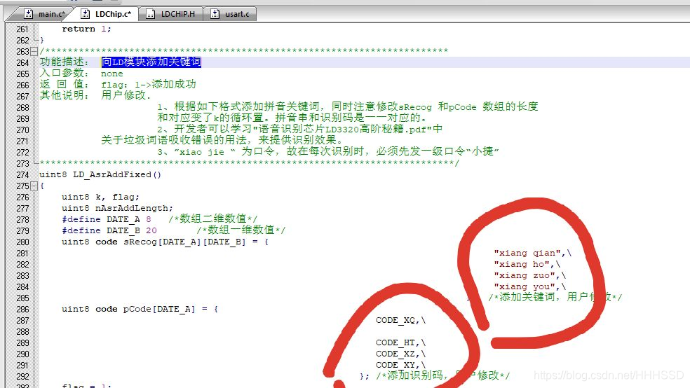
LD_AsrAddFixed();
/************************************************************************
功能描述: 向LD模块添加关键词
入口参数: none
返 回 值: flag:1->添加成功
其他说明: 用户修改.
					 1、根据如下格式添加拼音关键词,同时注意修改sRecog 和pCode 数组的长度
					 和对应变了k的循环置。拼音串和识别码是一一对应的。
					 2、开发者可以学习"语音识别芯片LD3320高阶秘籍.pdf"中
           关于垃圾词语吸收错误的用法,来提供识别效果。
					 3、”xiao jie “ 为口令,故在每次识别时,必须先发一级口令“小捷”
**************************************************************************/
uint8 LD_AsrAddFixed()
{
	uint8 k, flag;
	uint8 nAsrAddLength;
	#define DATE_A 8   /*数组二维数值*/
	#define DATE_B 20		/*数组一维数值*/
	uint8 code sRecog[DATE_A][DATE_B] = {	   //该部份是你想输入的语音口令的拼音
																				 "xiang qian",\
																				 "xiang ho",\
																				 "xiang zuo",\
																				 "xiang you",\
																			};	/*添加关键词,用户修改*/
	uint8 code pCode[DATE_A] = {               //该部分是对应着拼音来写的识别码
															CODE_XQ,\

															CODE_HT,\
															CODE_XZ,\
															CODE_XY,\
														 };	/*添加识别码,用户修改*/
	flag = 1;
	for (k=0; k<DATE_A; k++)
	{

		if(LD_Check_ASRBusyFlag_b2() == 0)
		{
			flag = 0;
			break;
		}

		LD_WriteReg(0xc1, pCode[k] );
		LD_WriteReg(0xc3, 0 );
		LD_WriteReg(0x08, 0x04);
		delay(1);
		LD_WriteReg(0x08, 0x00);
		delay(1);

		for (nAsrAddLength=0; nAsrAddLength<DATE_B; nAsrAddLength++)
		{
			if (sRecog[k][nAsrAddLength] == 0)
				break;
			LD_WriteReg(0x5, sRecog[k][nAsrAddLength]);
		}
		LD_WriteReg(0xb9, nAsrAddLength);
		LD_WriteReg(0xb2, 0xff);
		LD_WriteReg(0x37, 0x04);
	}
    return flag;
}
LD_AsrAddFixed();
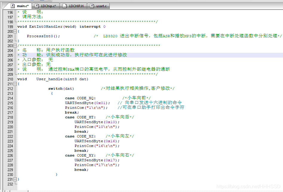
/***********************************************************
* 名    称:用户执行函数
* 功    能:识别成功后,执行动作可在此进行修改
* 入口参数: 无
* 出口参数:无
* 说    明: 通过控制PAx端口的高低电平,从而控制外部继电器的通断
**********************************************************/
void 	User_handle(uint8 dat)
{
			 switch(dat)		   /*对结果执行相关操作,客户修改*/
			  {
	                case CODE_XQ:			/*小车向前*/
					UARTSendByte(0x01);   // 向串口发送十六进制的命令
					PrintCom("1\r\n");	  //可在串口助手打印出命令字符
					break;
					case CODE_HT:	 /*小车向后*/
						UARTSendByte(0x10);
						PrintCom("10\r\n");
						break;
					case CODE_XZ:	 /*小车向左*/
						UARTSendByte(0x16);
						PrintCom("16\r\n");
						break;
					case CODE_XY:	 /*小车向右*/
						UARTSendByte(0x17);
						PrintCom("17\r\n");
						break;
				}
}
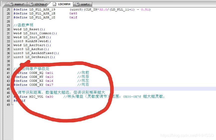
Find the code you need to modify yourself in the LDCHIP.H file
//识别码客户修改处
#define CODE_XQ 0x01			//向前
#define CODE_HT 0x10			//向后
#define CODE_XZ 0x16			//向左
#define CODE_XY 0x17			//向右
Next is the Arduino code (this code is the serial signal code of the receiving voice module. Every time the voice module receives an instruction, the corresponding pin of the Wemos chip will produce a corresponding level change. We can use this change to set the corresponding The pin is interrupted, because I think that everyone does not necessarily make a car, so I only sent this code to everyone to develop. You can use LED lights or buzzers to debug the corresponding pins. Of course, you can also use them. Oscilloscope)
#include<SoftwareSerial.h>    //需要调用这个库实现串口通信

void setup() {
 pinMode(D3,OUTPUT);        //设置IO口D3为输出模式
 pinMode(D4,OUTPUT);        //设置IO口D4为输出模式
  Serial.begin(9600);
  digitalWrite(D2,LOW);     //给D2口低电平
    digitalWrite(D3,LOW);     //给D3口低电平
  delay(3000);

}

void loop() {
  int cmd;


  if(Serial.available() > 0){
      cmd = Serial.read();
      switch(cmd)
        {
          case 1:          //前面提到的读取到1表示向前
            digitalWrite(D3,HIGH);//当喊“向前”时,可以看到Arduino上的D3会置高
            break;
          case 10:
            digitalWrite(D3,LOW);//当喊“向前”时,可以看到Arduino上的D3会置低
            break;

             break;
          case 0x16:
            digitalWrite(D4,HIGH);//当喊“向前”时,可以看到Arduino上的D4会置高
            break;
          case 0x17:
            digitalWrite(D4,LOW);//当喊“向前”时,可以看到Arduino上的D4会置低
            break;
           default:
            break;
        }


    }

}