Author: Liu Xin, Tech Gear automotive diagnostic outstanding college students engaged in vehicle maintenance JEEP brand for nearly 10 years by the Fiat Chrysler (FCA) Level 3 certification and expert technicians national vocational qualifications 2 / technician certification.
1. Failure phenomenon
A 2017 Dodge RAM 1500, equipped with TNXE-FE engine, has a cumulative mileage of approximately 31,000 kilometers. The owner of the car reported that recently, the car occasionally showed no compass display and the air conditioner did not work.
Two, fault diagnosis
Read the fault code with a fault detector (WITECH) and find that the fault code "U0184-00 Communication with the radio is interrupted" is stored in the air conditioning control module (HVAC); both are stored in the body control module (BCM) and the radio amplifier (AMP) There is a fault code "U0010-00 CAN internal bus"; the fault code "U0147-00 and telematics (vehicle information service system) gateway communication loss" is stored in the heated seat control module (HSM) and BCM. It is inferred that the vehicle has a communication fault.
As shown in Figure 1, the vehicle communication bus is mainly divided into two parts. The right side of the BCM is the vehicle body and internal system communication bus (ie CAN IHS bus), the transmission speed is 125 kbit/s, and the left side of the BCM is the power system communication bus. (That is CAN C bus), the transmission speed is 500 kbit/s, BCM is the central gateway, responsible for connecting the CAN IHS bus and CAN C bus to meet the communication requirements between the two. The car’s radio (RADIO) functions as a telematics gateway to satisfy the communication between audio systems. Both CAN IHS bus and CAN C bus adopt star architecture, and all modules are connected through 2 star connectors. In addition, the CAN IHS bus is connected to the data diagnostic interface (DLC) terminal 3 (CAN H terminal) and terminal 11 (CAN L terminal), and the CAN C bus is connected to the data diagnostic interface (DLC) terminal 6 (CAN H terminal) and terminal 14. (CAN L terminal).
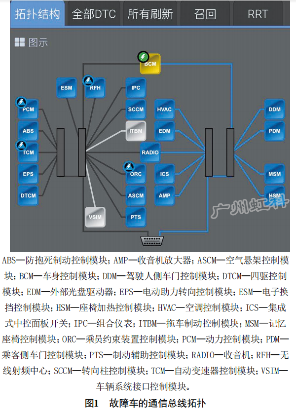
Since the modules storing the fault codes are all on the CAN IHS bus, it is inferred that the CAN IHS bus communication is faulty. Disconnect the negative terminal of the battery, use a multimeter to measure the resistance between DLC terminal 3 and terminal 11 (that is, the terminal resistance of the CAN IHS bus), and it is 61.7 Ω, which is normal. Use pico oscilloscope to measure the communication waveform on the CAN IHS bus (Figure 2) and find that the voltage on the CAN H line is pulled up from about 0.9 V to about 3.3 V (normally it should be pulled up from about 2.5 V to about 3.5 V), CAN L line The voltage on the upper side is quickly pulled down from about 0.8 V to 0 V, and then pulled up to about 1.2 V (normally it should be pulled down from about 2.5 V to about 1.5 V), thereby confirming that the CAN IHS bus communication is faulty.

It can be seen from Figure 3 that the modules on the CAN IHS bus are connected by the combination meter star connector and the body star connector.

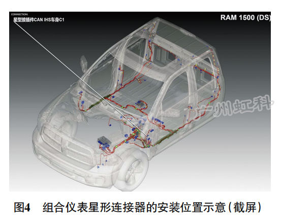
Check the maintenance data to know the installation positions of the combination meter star connector and the body star connector are shown in Figure 4 and Figure 5. Find the star connector of the combination meter, and first disconnect its wire connector C1 (the only 3-terminal wire connector, the others are 2-terminal), so that the star connector of the combination meter is connected to the star connector of the vehicle body The control module was isolated. As a result, the communication waveform on the star connector side of the combination meter returned to normal, the communication waveform on the star connector side of the vehicle body remained the same, and the fault code "U0010-00 CAN internal bus" was still stored in the BCM. It is inferred that the fault occurred on the control module or circuit on the side of the star connector of the vehicle body.

Locate the star connector of the vehicle body and disconnect the upper 2-terminal wire connector in turn. When the wire connector C3 (connected to the driver's door control module) is disconnected, the communication waveform returns to normal. Remove the door trim on the driver's side and find that the car is equipped with an automatic window lift control module, and the control module is connected to the CAN IHS bus through the communication line on the driver's door control module.
Three, troubleshooting
After removing the installed automatic window lifting control module, the communication waveform returned to normal, the fault disappeared, and the fault was eliminated.
Four, fault summary
Carefully analyze the communication waveform at the time of the failure, and infer that the failure of the vehicle is caused by a short circuit of the CAN L line on the CAN IHS bus. At this time, the voltage on the CAN L line is struggling between 0 V and 1.2 V, and the communication capability is completely lost, while the recessive voltage on the CAN H line drops to about 0.9 V (normally should be about 2.5 V), and the dominant voltage is basically unchanged , Is about 3.3 V (normally should be about 3.5 V), still has a certain communication ability.