void TD_Init( void )
{ // Called once at startup
CPUCS= 0x12; // CLKSPD[1:0]=10, for 48MHz operation, output CLKOUT
SYNCDELAY;
REVCTL = 0x03; // REVCTL.0 and REVCTL.1 set to 1
SYNCDELAY;
PINFLAGSAB = 0x08; // FLAGA- EP2EF (EP2 empty flag) // EP2 OUT
SYNCDELAY;
= 0x0E PINFLAGSCD; // FLAGC - EP6FF ( EP6 full flag) // EP6 the IN
SYNCDELAY;
// PORTACFG | = 0x80; // PA7 multiplexing is FLAGD
//SYNCDELAY;
IFCONFIG= 0x63; //Internal clock, 48 MHz, Slave FIFO interface
// set externalclock is 0x63, 5MHz-48MHz
SYNCDELAY;
Definition information bit register // IFCONFIG
//IFCLKSRC=1 , FIFOs executes on internalclk source
//xMHz=1 , 48MHz operation
//IFCLKOE=1 ,Drive IFCLK pin signal at48MHz
//IFCLKPOL=0 , Don't invert IFCLK pinsignal from internal clk
//ASYNC=0 , master samples synchronous
//GSTATE=0 , Don't drive GPIF statesout on PORTE[2:0], debug WF
//IFCFG[1:0]=11, FX2 in slave FIFO mode
//Note: The pre-REVE EPxGPIFTCH/L register are affected, as well...
// ...these have been replaced byGPIFTC[B3:B0] registers
// previous versions EPxGPIFTCH / L register has been GPIFTC [B3: B0] replaced Register
// EP4 and EP8 are not used in this implementation ... here are not used EP4 and EP8 endpoint
EP1OUTCFG= 0xA0;
SYNCDELAY;
EP1INCFG= 0xA0;
SYNCDELAY;
EP2CFG = 0xAA; // out 512 / 1024bytes, 2x, bulk; wherein the b5 / b4 bit (TYPE1 / TYPE0) compared to bulk transfer mode 10
SYNCDELAY;
EP6CFG= 0xEA; // in 512/1024bytes, 2x, bulk
SYNCDELAY;
EP4CFG= 0x02; //clear valid bit
SYNCDELAY;
EP8CFG= 0x02; //clear valid bit
SYNCDELAY;
// FIFORESET reset state for FIFO
FIFORESET = 0x80; // Activate NAK-allt void race conditions
SYNCDELAY; // see TRM section 15.14
FIFORESET = 0x02; // reset, rising 2
SYNCDELAY; //
FIFORESET = 0x04; // reset, rose 4
SYNCDELAY; //
FIFORESET= 0x06; // reset, FIFO 6
SYNCDELAY;
FIFORESET = 0x08; // reset, rose 8
SYNCDELAY; //
FIFORESET= 0x00; // deactivate NAK-ALL
SYNCDELAY;
// handle the case where we were already in AUTO mode ... EP2 set to automatically output the 16-bit mode
//...for example: back to back firmware downloads ... EP6 set input 16 to Auto Mode
/*EP2BCL= 0x80; // arm EP2OUT bywriting byte count w/skip.
SYNCDELAY;
EP2BCL= 0x80; // arm EP2OUT bywriting byte count w/skip.
SYNCDELAY;
OUTPKTEND= 0x82; // Arm both EP2 buffers toPrime the pum
SYNCDELAY;
OUTPKTEND= 0x82; // Arm both EP2 buffers toPrime the pum
SYNCDELAY;
//core needs to see AUTOOUT=0 to AUTOOUT=1 switch to arm endp's
EP2FIFOCFG= 0x00; // AUTOOUT=0,WORDWIDE=1
SYNCDELAY; //
EP2FIFOCFG= 0x10; // AUTOOUT=1,WORDWIDE=1
SYNCDELAY;*/
// If the data does not satisfy the IN data transport packet buffer size requirements, such as a package for bulk transfer IN 1024,
// If the buffer size is 10 bytes of data, may be submitted through INPKTEND
//INPKTEND= 0x84; // Arm both EP6 buffers toPrime the pum
//SYNCDELAY;
//INPKTEND= 0x84; // Arm both EP6 buffers toPrime the pum
//SYNCDELAY;
EP6FIFOCFG= 0x00;
SYNCDELAY; //
EP6FIFOCFG = 0x08; // AUTOIN = 1, 1 = ZEROLENIN, WORDWIDE = 0 (8BIT)
SYNCDELAY; //
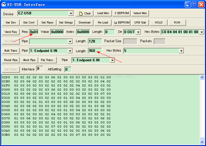
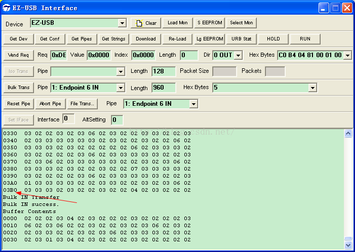
EP6BCH = 0x03; // arm EP6OUT by writing bytecount w/skip.
SYNCDELAY;
EP6BCL = 0xC0; // arm EP6OUT by writing bytecount w/skip.
SYNCDELAY;
EP6BCH = 0x03; // arm EP6OUT by writing bytecount w/skip.
SYNCDELAY;
EP6BCL = 0xC0; // arm EP6OUT by writing bytecount w/skip.
SYNCDELAY;/**/
FIFOPINPOLAR= 0x00; // set all slave FIFO interface pins as active low
SYNCDELAY;
EP6AUTOINLENH = 0x03; // EZ-USBautomatically commits data in 512-byte chunks03
SYNCDELAY;
EP6AUTOINLENL = 0xC0; //c0
SYNCDELAY;
// JTAG Enable and SYNC signals for ZTEXSpartan 6 module 1.1 (FGPA + FX2LP setup)? ? ? What is the role of the port FX2LP and ZTEX
PORTACFG&= 0xFD;
SYNCDELAY;
OEA|=0x02;//Declare PA.1 as output... SLWR
SYNCDELAY;
IOA|=0x02;//output 1 on PA.1
SYNCDELAY;
//OEC&=0x01;//PC.0 as output (SYNC signal) PC.0 synchronization signal
//SYNCDELAY;
//IOC|=0x00;//output 0 on PC.0...SYNC signal is LOW
//SYNCDELAY;
OED & = 0xFE; // PD.0 as input (Clock changing signal) PD.0 internal and external clock switching signal
SYNCDELAY;
// enable dual autopointer feature
AUTOPTRSETUP | = 0x01;
PORTACFG &= 0x7F;
SYNCDELAY;
OEA | = 0x80; // make PA7 output port , PA7 then SLWR write valid signal
SYNCDELAY;
IOA & = 0x7F; // make PA7 is set 0
SYNCDELAY;
IOA // | = 0x80;
//SYNCDELAY;
//Configure for external interrupts
PORTACFG | = 0x01; // configure PORTA PA0 to INT0
SYNCDELAY;
TCON | = 0x01; // INT0 valid on the falling
SYNCDELAY;
IE | = 0x81; // enable global interrupt, INT0 interrupt enable
SYNCDELAY;
}
void TD_Poll( void )
{ // Called repeatedly while the device isidle
if(IOD & 0x01)
{
done_frm_fpga =1;
}
if ((done_frm_fpga) && (IOD & 0x01)) // if PC.1 when input is low, switch to the external input clock, and the counter then PC.0 will ( synchronization signal ) is high
{
//IFCONFIG =0x63; //external clock input, Slave FIFOinterface
//SYNCDELAY;
PORTACFG &=0xFD;
SYNCDELAY;
XXIII | = 0x02;
SYNCDELAY;
IOA &=0xFD;//output 1 on PA.1...SLWR signal is HIGH
SYNCDELAY;
done_frm_fpga =0;
}
if(!(EP2468STAT &bmEP6FULL)) //ENDPOINT6 FIFO满
{
FIFORESET = 0x80; // Activate NAK-allt void race conditions
SYNCDELAY; // see TRM section 15.14
FIFORESET =0x06; // reset, FIFO 6
SYNCDELAY;
FIFORESET =0x00; // deactivate NAK-ALL
SYNCDELAY; /**/
EP6BCH = 0x03; // arm EP6OUT by writing bytecount w/skip.
SYNCDELAY;
EP6BCL =0xC0; // arm EP6OUT bywriting byte count w/skip.
SYNCDELAY;
EP6BCH =0x03; // arm EP6OUT bywriting byte count w/skip.
SYNCDELAY;
EP6BCL =0xC0; // arm EP6OUT bywriting byte count w/skip.
SYNCDELAY;
EP6AUTOINLENH = 0x03; // EZ-USBautomatically commits data in 512-byte chunks03
SYNCDELAY;
EP6AUTOINLENL =0xC0; //c0
SYNCDELAY;
}
INTSETUP &= ~bmAV4EN; // Disable INT4 autovectoring so that weuse the external INT4
}