Author: Wei Dongshan
Reference document:
. A Kernel Documentation \ under devicetree \ bindings \ Pinctrl \ directory:
Pinctrl-bindings.txt
b Kernel Documentation \ directory under gpio:.
Pinctrl-bindings.txt
. c kernel Documentation \ under devicetree \ bindings \ gpio directory:
gpio.txt
Note: The focus of this chapter is to "use" in-depth explanation on the "Driver bible" of the video.
In front of the video, we use a direct write operation of register drive. This is just to let everyone grasp the essence of the driver, we do not do so in the actual development process, a very inefficient! If you are so driven development to find the register, then we become "register engineers", and even do not cling to the bare microcontroller write a register.
Under Linux for the pin has two important subsystems: GPIO, Pinctrl.
1.Pinctrl subsystem important concepts
1.1 introduced
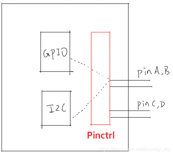
No matter what kind of chip, has a similar structure in the figure below:
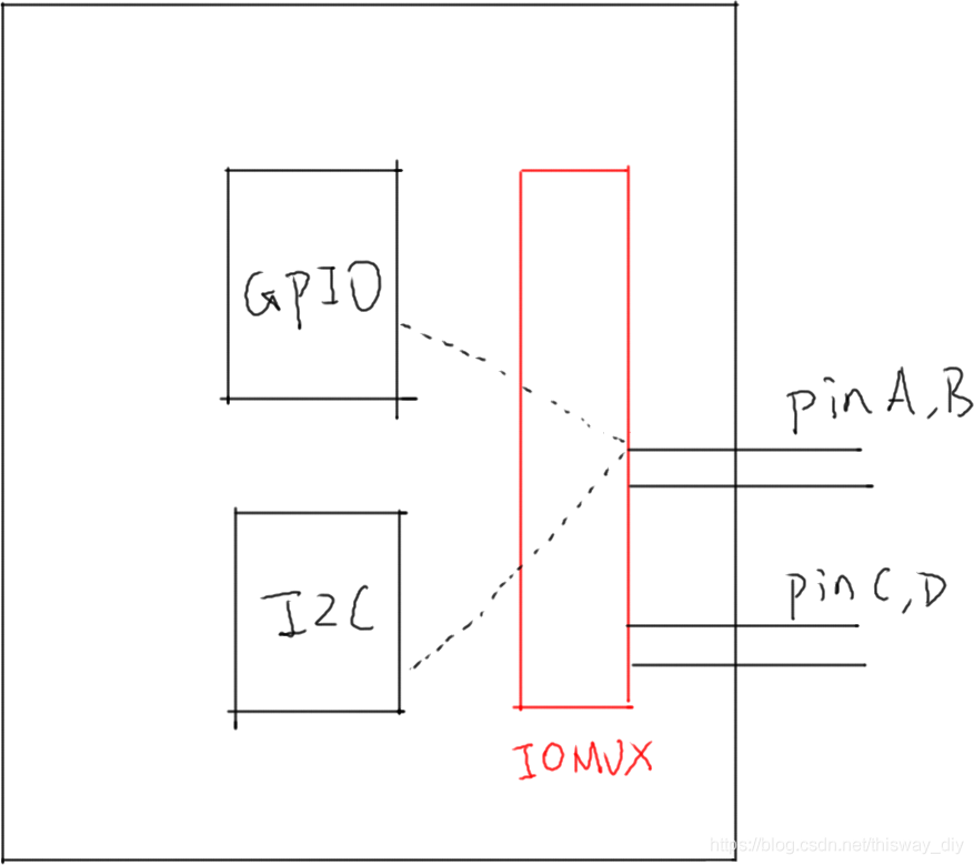
To get pinA, B for GPIO, needs to be set so that they are connected to IOMUX GPIO module;
to get pinA, B for I2C, IOMUX need to set them on the I2C module.
So GPIO, I2C should be juxtaposed relationship, before they can use, you need to set IOMUX. Sometimes not just set IOMUX, but also configuration pins, such as pull-up, pull-down, open-drain, and so on.
Now several hundred pins of the chip, while using the GPIO feature that lets you pin a pin to find a corresponding register, which is to be mad. Industry specializing in surgery, so hard to let these chip manufacturers do it ── they are BSP engineer. We develop on their basis, we are driven engineers. Joke, BSP engineers know better his own chips, but if you drive engineers do not understand their code, that your progress is limited ah.
Therefore, should the pin multiplexing, to configure out, made Pinctrl subsystem, a GPIO, I2C other modules.
What BSP Engineers do? Look:
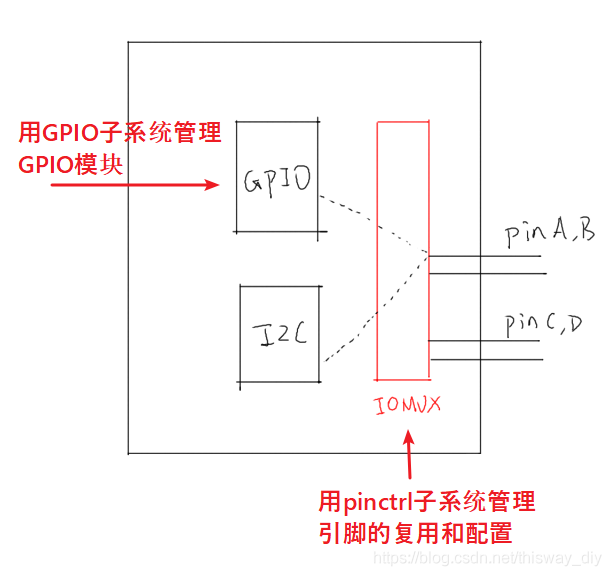
such as BSP engineers GPIO subsystem, Pinctrl subsystem to support its own chip after added to the list, we can very easily use these pins: the lighting is simply too simple.
Etc., GPIO with the I2C module in the figure are not parallel it? Why talking about Pinctrl Shihai GPIO subsystem to pull in?
Most of the chip, no separate module IOMUX pin multiplexing, configuration, etc., within the GPIO module is implemented.
GPIO and Pinctrl is so closely related to the hardware, the software on their relationship is very close.
So we explain these two subsystems together.
1.2 Key Concepts
From the device tree will be easier to start learning Pintrl.
The main reference documents are: Kernel Documentation \ devicetree \ bindings \ pinctrl \ pinctrl-bindings.txt
This involves two objects: pin controller, client device.
The former provides services: You can use it to multiplexed pins, configuration pins.
The latter use the service: What features to declare which pins they have to use, how to configure them.
a pin controller:.
in the chip you can not find the manual pin controller, it is a concept of software, you can think it corresponds IOMUX── for multiplexed pins, pins can also be configured (such as a pull-down resistor, etc. ).
Note, pin controller and the Controller GPIO not the same, the former may be used to control the GPIO function pin, I2C function; the latter is only pin is configured as input, output and other simple functions.
b. Client Device
"client device", whose clients? Customer Pinctrl systems that use equipment Pinctrl system, using the device pins. It will be defined in the device tree as a node, a node in a statement in which pins to use.
FIG following several important concepts can put clear rationale:
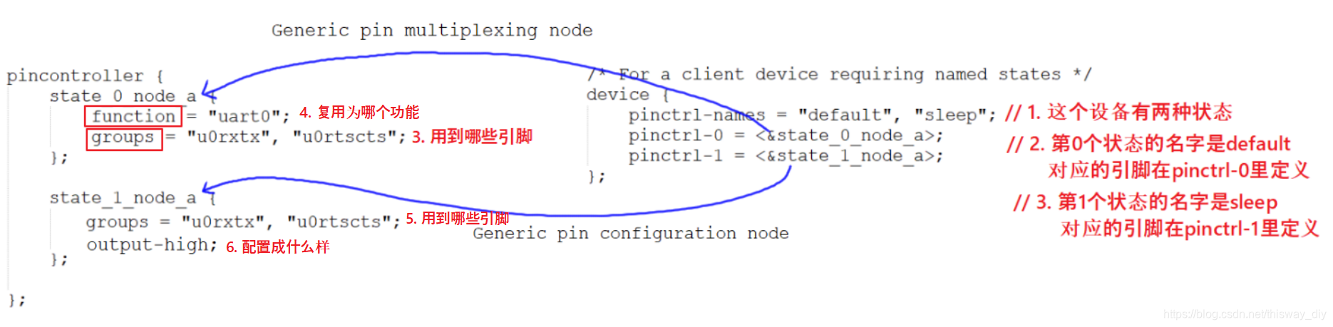
figure above, pincontroller left node is the right node client device:
A PIN State:.
For a "client device" is, for example, a UART device, which has a plurality of "status": default, sleep, etc., that pin may also have these states.
How to understand?
For example, by default, UART device is working, then the pin will be used alternately as UART functions.
In the sleep state to conserve power, these pins can be multiplexed as GPIO functions; or configure them directly outputs a high level.
Figure above, pinctrl-names in the definition of two states: default, sleep.
0 states pin definitions used in pinctrl-0, which is state_0_node_a, located pincontroller node.
The first pin is defined states used in pinctrl-1, which is state_1_node_a, located pincontroller node.
When this device is in the default state, pinctrl subsystem automatically said information to be used according to uart0 pin multiplexing function.
When this device is in the sleep state, pinctrl subsystem automatically based on the information used to configure the pins is high.
. b groups and function:
a device will use one or more pins that can be classified as a group (Group);
these pins may be multiplexed as a function: function.
Of course: a multi-pin device can be used, such as A1, A2 two pins A1 to F1 multiplexing functional group, A2 is a group multiplexing function F2.
c. Generic pin multiplexing node and Generic pin configuration node
in the left side of FIG pin controller node, the node has child or grandchild node, which are used for client device.
It can be used to describe the multiplexing information: which group (group) which pins are multiplexed with the function (function);
can be used to describe the configuration information: which group (group) which pin is configured as setting function (setting), such as pull-on , drop down and so on.
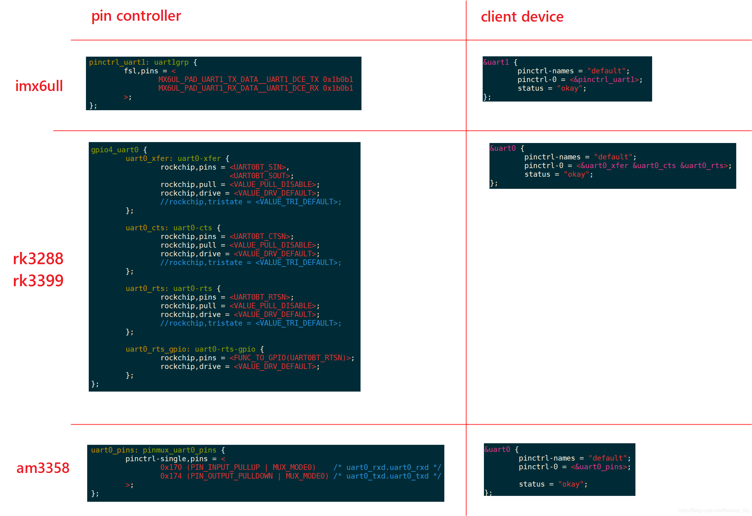
Note: The format pin controller node, there is no uniform standard! ! ! ! Each chip is different.
Even the above group, function key does not necessarily have, but the concept is there.
1.3 Example

How references pinctrl 1.4 code
It is clear that our basic drives do not control. When the switching state of the device, will be called corresponding pinctrl.
For example, in the enumeration process and platform_driver platform_device, the procedure is as follows:
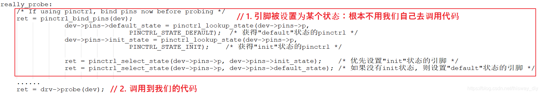
when the system is dormant, also to set the sleep state of the device corresponding to the pin, we do not need to own calling code.
Have to call their own, there are functions:
devm_pinctrl_get_select_default(struct device *dev);      // 使用"default"状态的引脚
pinctrl_get_select(struct device *dev, const char *name); // 根据name选择某种状态的引脚
pinctrl_put(struct pinctrl *p);   // 不再使用, 退出时调用
2.GPIO subsystem important concepts
2.1 introduces
To operate the GPIO pins, first pin is configured to use the GPIO function, which is achieved by Pinctrl subsystem.
Can then be set according to the pin direction (input or output), reading obtained ── level state, the write value ── high and low output.
Before we GPIO pin operated by a register, even if the LED drivers for different boards that are completely different code.
When the BSP engineers achieved GPIO subsystem, we can:
. A specified in the device tree GPIO pins
b in the driver code:
the use of standard functions obtained GPIO GPIO subsystem, provided GPIO direction, Read / Set GPIO value.
Such driver code, the board would be irrelevant.
2.2 specified in the device tree pin
In almost all of the ARM chip, the GPIO are divided into groups, each group has a number of pins. So before using GPIO subsystem, you must first determine: Which group is it? Group in which one?
In the device tree, "GPIO group" is a GPIO Controller, which is usually set by the chip manufacturer. We need to do is to find its name, such as "gpio1", and then specify which pin to use it inside, such as <& gpio1 0>.
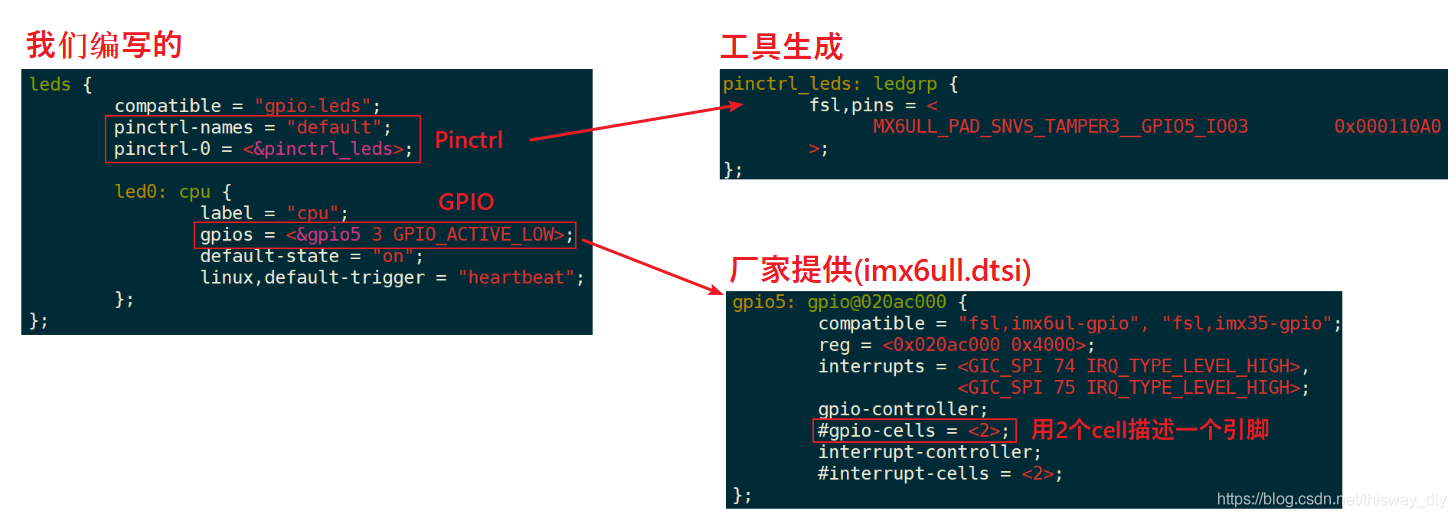
There code more intuitive, the GPIO controller node figure is the number of chips, they are generally well defined by the manufacturer, in xxx.dtsi file:
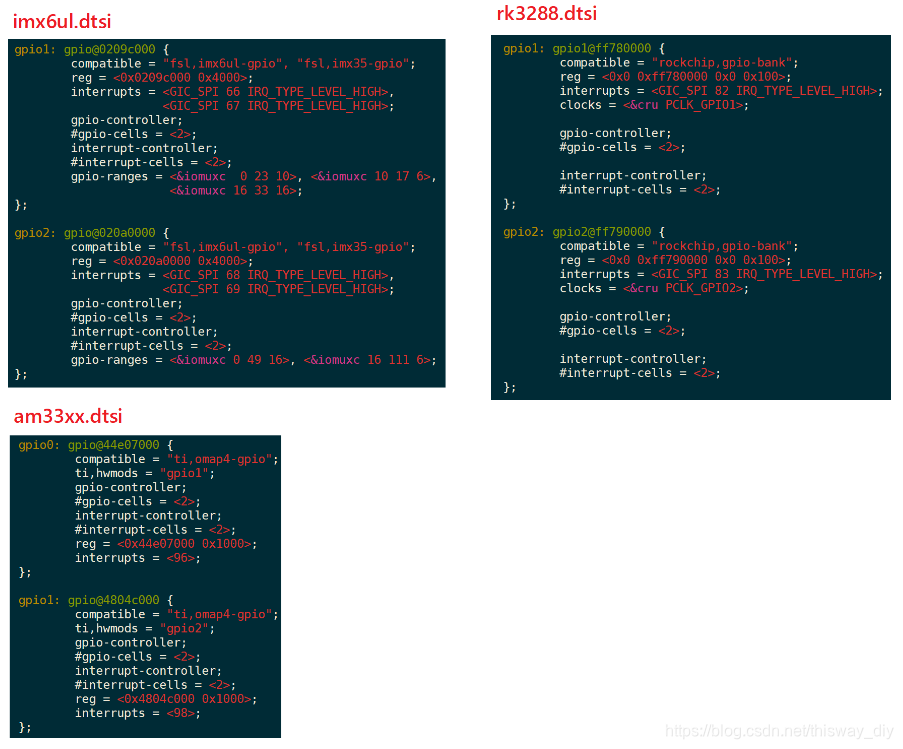
We do need to be concerned only inside these two attributes:
gpio-controller;
#gpio-cells = <2>;
"Gpio-controller" indicates that this node is a GPIO Controller, below it there are a lot of pins.
"# Gpio-cells = <2 >" denotes two 32-bit numbers each pin of the controller to use this (cell) is described.
Why use two numbers? In fact, the use of multiple cell to describe a pin, which is GPIO Controller own decisions. Wherein a cell can be used for example to indicate that a pin which, with another cell to indicate that it is active high or active low, and even more may be used to illustrate other cell characteristics.
Common usage is to use a cell of a pin which is represented by the second cell to represent a valid level:
GPIO_ACTIVE_HIGH : 高电平有效
GPIO_ACTIVE_LOW  :  低电平有效
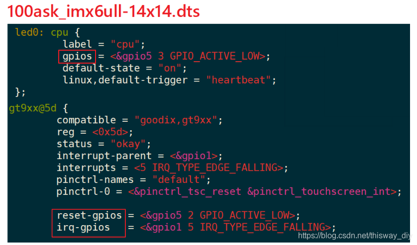
Is defined GPIO Controller chip manufacturers do, how we refer to a pin of it? Using its own node device attribute "[-] gpios", examples are as follows:

Figure above, may be used GPIOs properties, may be used name-gpios property.
2.3 GPIO subsystem calls the driver code
GPIO pins are specified in the device tree, how to use the driver code?
That is what GPIO interface subsystem functions are?
GPIO subsystem has two interfaces: based descriptor (descriptor-based), old (legacy). The former have the function prefix "gpiod_", it is represented using gpio_desc a pin structure; the latter function has the prefix "gpio_", which uses a pin to represent an integer.
To operate a pin, you must first get the pin, and then set the direction of reading, writing value.
To be included in the driver header file,
#include <Linux / GPIO / consumer.h> // descriptor-based
or
#include <linux / gpio.h> // legacy
The following table lists common functions:
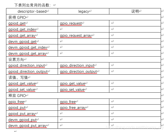
Prefix "devm_" means "Device Explorer" (Managed Device Resource), which is an automatic mechanism for release of resources. The idea is "resource belongs to the device, the device does not exist when resources can be automatically released."
For example, in Linux development process, first apply a GPIO, and then apply for a memory; if memory allocation fails, before returning on the need to release the GPIO resources. If you are using the correlation function devm, and when memory fails you can apply for direct return: the destruction of the device will function automatically releases have applied for the GPIO resources.
It recommended "devm_" version of the correlation function.
For example, the device prosthetic device has the following node in the tree:
	foo_device {
		compatible = "acme,foo";
		...
		led-gpios = <&gpio 15 GPIO_ACTIVE_HIGH>, /* red */
			    <&gpio 16 GPIO_ACTIVE_HIGH>, /* green */
			    <&gpio 17 GPIO_ACTIVE_HIGH>; /* blue */

		power-gpios = <&gpio 1 GPIO_ACTIVE_LOW>;
	};
You can use the following function to get the pin:
struct gpio_desc *red, *green, *blue, *power;
red = gpiod_get_index(dev, "led", 0, GPIOD_OUT_HIGH);
green = gpiod_get_index(dev, "led", 1, GPIOD_OUT_HIGH);
blue = gpiod_get_index(dev, "led", 2, GPIOD_OUT_HIGH);
power = gpiod_get(dev, "power", GPIOD_OUT_HIGH);
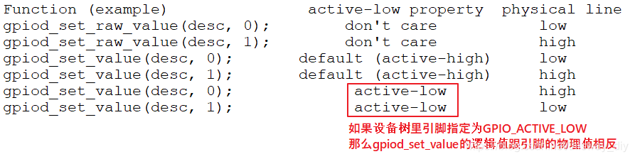
It is noted that, setting the value gpiod_set_value is "logical value", not necessarily equal to the physical value.
What does this mean?
The old "gpio_" function can not be obtained according to the pin device tree information, it needs to know the pin number.
How to determine the pin number?
In GPIO subsystem, each register will determine its "base number" when a GPIO Controller, then the controller in the n-th pin number is: base number + n.
But if the hardware changes, there are changes in the device tree, the base number and can not be guaranteed to be fixed, you should check sysfs to determine base number.
A method of accessing 2.4 sysfs
Access in sysfs GPIO, in fact, is the use of pin numbers, the old method.
a. determining a first reference pin GPIO Controller Number (base number), and then calculate a number of pins.
As follows:
① In the first development board / sys / class / gpio directory, the directory to find each gpiochipXXX:
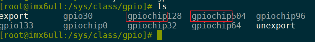
② gpiochip then enter a catalog, view the contents of the file label
③ Comparative tree apparatus according to the content of the label
label content from a device tree, such as its base address register. Used with the device tree (dtsi file) comparison, we can know that which corresponds to a GPIO Controller.
The figure is the result of running on 100asK_imx6ull, gpiochip96 seen by comparing the device tree corresponds gpio4:
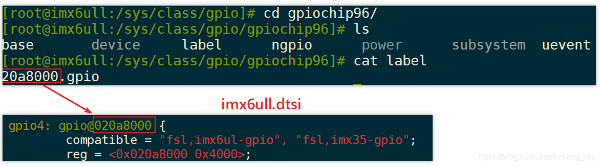
So this set of pins GPIO4 reference pin number is 96, which may be "cat base" to confirm again.
b Based on the pin sysfs:
In 100ask_imx6ull example, it has a button, the following diagram:
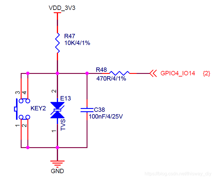
so GPIO4_14 number is 96 + 14 = 110, the operation reads the key values may be as follows:
echo  110 > /sys/class/gpio/export
echo in > /sys/class/gpio/gpio110/direction
cat /sys/class/gpio/gpio110/value
echo  110 > /sys/class/gpio/unexport
Note: If the driver is already using this pin, it will export fails, it will prompt the following error:

For the output pin, pin number is assumed as N, its value may be provided by one of the following methods:
echo  N > /sys/class/gpio/export
echo out > /sys/class/gpio/gpioN/direction
echo 1 > /sys/class/gpio/gpioN/value
echo  N > /sys/class/gpio/unexport
3. Based on an LED driver subsystem GPIO
3.1 Programe
GPIO status with other modules, such as I2C, UART is the same place, you want to use a pin, you need to first pin is configured as GPIO function, which is to be used Pinctrl subsystem, you can simply specify the device tree . We do not need to do anything on the drive code.
GPIO pins need to identify itself, it also needs to be specified in the device tree.
Kernel device tree node is converted to platform_device.
Corresponding to the driver code platform_driver a register, in the probe function: obtaining pin register file_operations.
In the file_operations: setting direction, the value of the read / write value.
The figure is an example of a device tree:
3.2 Add Pinctrl information in the device tree
Some chips provided an apparatus tree generation means, and selection pin function configuration information in the GUI interface, it can be automatically generated Pinctrl child node. Copy it to your device file tree, then you can reference node in the client device.
Some chips provide only documents, then go read the documentation, usually in the kernel source directory Documentation \ devicetree \ bindings \ pinctrl below, the preservation of the manufacturer's documentation.
Even if the documents are not, you can only refer to the device tree file in the kernel sources in the kernel source directory arch / arm / boot / dts directory.
The final step, the search network.
Style Pinctrl child nodes as follows:
3.3 Add the information in the device tree GPIO
First check circuit diagram pin used is determined, then the device specified in the tree: Add "[name] -gpios" attribute, which specifies the use of a GPIO Controller in which one pin, Flag other information, such as GPIO_ACTIVE_LOW Wait. How many cell specific needs to describe a pin, need to see property values "# gpio-cells" in the device tree node in the GPIO Controller, you can also view the kernel documentation.
Examples are as follows:
3.4 Programming Example
In actual operation you may encounter unexpected problems, a live demonstration of how to solve.
. a defined, a register platform_driver
B in its probe function:.
B.1 determined according platform_device GPIO device tree information: gpiod_get
B.2 defined, a register structure file_operations
b.3 GPIO subsystem used in file_operarions functions operate the GPIO:
gpiod_direction_output, gpiod_set_value
Benefits: This code is exactly the same for all of the code!
After using GIT command set, the source leddrv.c located in this directory:
01_all_series_quickstart\
04_快速入门_正式开始\
02_嵌入式Linux驱动开发基础知识\source\
05_gpio_and_pinctrl\
    01_led
Excerpt Highlights:
. A registered platform_driver
attention on line 122 following "100ask, leddrv", which would correspond to a node compatible with the device tree:
121 static const struct of_device_id ask100_leds[] = {
122     { .compatible = "100ask,leddrv" },
123     { },
124 };
125
126 /* 1. 定义platform_driver */
127 static struct platform_driver chip_demo_gpio_driver = {
128     .probe      = chip_demo_gpio_probe,
129     .remove     = chip_demo_gpio_remove,
130     .driver     = {
131         .name   = "100ask_led",
132         .of_match_table = ask100_leds,
133     },
134 };
135
136 / 2. * * function register platform_driver inlet /
137 static int __init led_init(void)
138 {
139     int err;
140
141     printk("%s %s line %d\n", __FILE__, __FUNCTION__, __LINE__);
142
143     err = platform_driver_register(&chip_demo_gpio_driver);
144
145     return err;
146 }
b. Obtain probe GPIO function in
the core code is the line 87, it gets the pin called "led" from the device (the device corresponding to the node in the device tree). In the device tree, there must be an attribute called "led-gpios" or "led-gpio".
77 /* 4. 从platform_device获得GPIO
78  *    把file_operations结构体告诉内核:注册驱动程序
79  */
80 static int chip_demo_gpio_probe(struct platform_device *pdev)
81 {
82      //int err;
83
84      printk("%s %s line %d\n", __FILE__, __FUNCTION__, __LINE__);
85
86      /* 4.1 设备树中定义有: led-gpios=<...>; */
87     led_gpio = gpiod_get(&pdev->dev, "led", 0);
88      if (IS_ERR(led_gpio)) {
89              dev_err(&pdev->dev, "Failed to get GPIO for led\n");
90              return PTR_ERR(led_gpio);
91      }
92
c registered file_operations structure:
This is the old routine:
93      /* 4.2 注册file_operations      */
94      major = register_chrdev(0, "100ask_led", &led_drv);  /* /dev/led */
95
96      led_class = class_create(THIS_MODULE, "100ask_led_class");
97      if (IS_ERR(led_class)) {
98              printk("%s %s line %d\n", __FILE__, __FUNCTION__, __LINE__);
99              unregister_chrdev(major, "led");
100             gpiod_put(led_gpio);
101             return PTR_ERR(led_class);
102     }
103
104     device_create(led_class, NULL, MKDEV(major, 0), NULL, "100ask_led%d", 0); /* /dev/100ask_led0 */
105
. D function call GPIO pins disposed in the direction of the open function:
51 static int led_drv_open (struct inode *node, struct file *file)
52 {
53      //int minor = iminor(node);
54
55      printk("%s %s line %d\n", __FILE__, __FUNCTION__, __LINE__);
56      /* 根据次设备号初始化LED */
57      gpiod_direction_output(led_gpio, 0);
58
59      return 0;
60 }
. E function call GPIO pin disposed in the write function values:
34 /* write(fd, &val, 1); */
35 static ssize_t led_drv_write (struct file *file, const char __user *buf, size_t size, loff_t *offset)
36 {
37      int err;
38      char status;
39      //struct inode *inode = file_inode(file);
40      //int minor = iminor(inode);
41
42      printk("%s %s line %d\n", __FILE__, __FUNCTION__, __LINE__);
43      err = copy_from_user(&status, buf, 1);
44
45      /* 根据次设备号和status控制LED */
46      gpiod_set_value(led_gpio, status);
47
48      return 1;
49 }
. F release GPIO:
gpiod_put(led_gpio);
4. The machine experiment 100ASK_IMX6ULL
4.1 determining device tree node and generates pin
For IMX6ULL chip company NXP, we have the device tree generation tool. We also upload it to go GIT, GIT using the load command, in this directory:
01_all_series_quickstart\
04_快速入门_正式开始\
02_嵌入式Linux驱动开发基础知识\source\
05_gpio_and_pinctrl\
tools\
imx\
Run after installation "Pins_Tool_for_i.MX_Processors_v6_x64.exe", open IMX6ULL profile "MCIMX6Y2xxx08.mex", you can choose pin in the GUI interface, configure its function, which can automatically generate a child node of information Pinctrl.
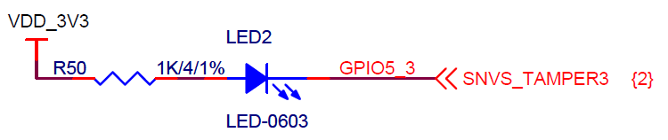
Schematic 100ASK_IMX6ULL LED used below, the pin is found GPIO5_3:
the device tree tool, operation as shown below:
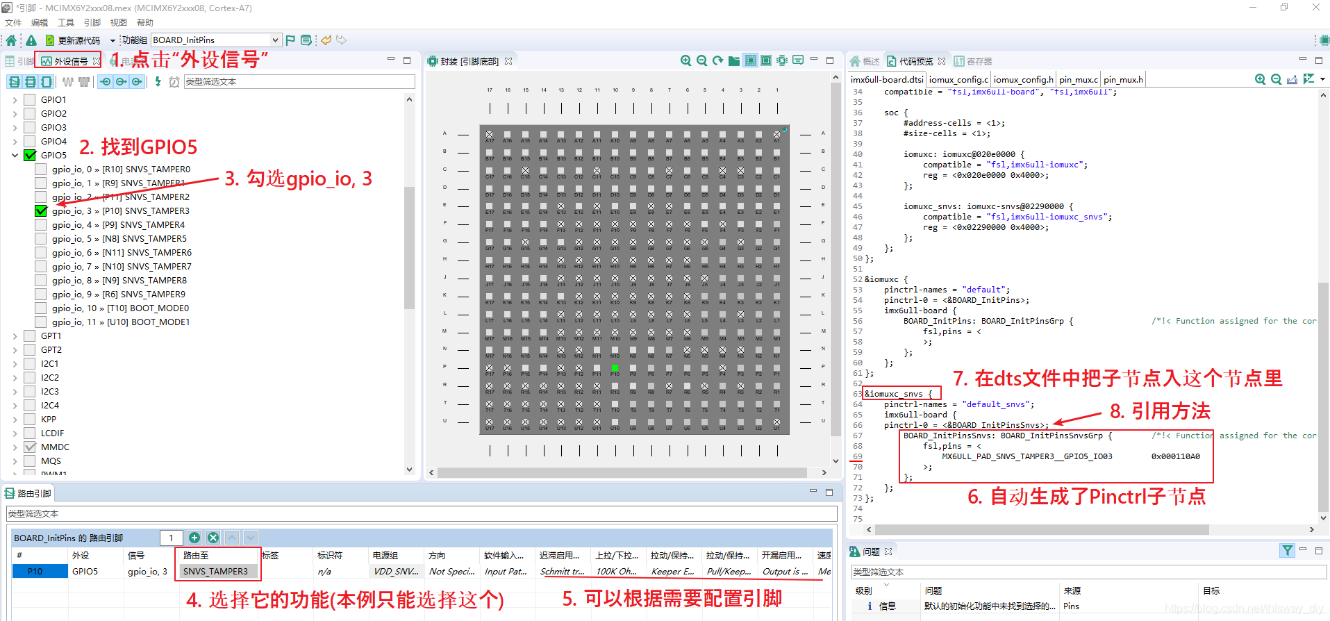
The automatically generated device information tree, the kernel source into the arch / arm / boot / dts / 100ask_imx6ull-14x14.dts code is as follows:
. A Pinctrl information:
&iomuxc_snvs {
……
        myled_for_gpio_subsys: myled_for_gpio_subsys{
            fsl,pins = <
                MX6ULL_PAD_SNVS_TAMPER3__GPIO5_IO03        0x000110A0
            >;
        };
. B equipment node information (on the root):
        myled {
            compatible = "100ask,leddrv";
            pinctrl-names = "default";
            pinctrl-0 = <&myled_for_gpio_subsys>;
            led-gpios = <&gpio5 3 GPIO_ACTIVE_LOW>;
        };
4.2 compiler
After compiling the device tree, you want to update the device tree.
When compiling the driver, "leddrv_ untested original version .c" is the error message, "leddrv.c" is modified.
Test methods, execute commands on the board:
#insmod  leddrv.ko
#ls /dev/100ask_led0
#./ledtest /dev/100ask_led0 on
#./ledtest /dev/100ask_led0 off
