Twinning project
| project | content |
|---|---|
| This work belongs to the Northern Spring 2020 Software Engineering | Blog class connection Park |
| Belongs classes | 006 |
| This job is a job of this course twinning projects | Work requirements |
| My aim in this course is | Harvest team project development experience, to improve their software development level |
| In particular aspects of the job which helped me achieve goals | Pair programming experience |
| Item code | Github repository |
demand analysis
And work on a personal project similar to this lies in solving mission-critical intersection. As for the new demands "intersection draw" is a simple extension, in fact, the coordinates of each point of intersection of feedback to the user.
The mission added two graphics: line segments and rays, which are a special line. Why is the special "straight line" mean? Because in essence, both the graphics are infinite straight line cut and formed.
Because of this nature, we find that the whole process of solving almost unchanged. The last time the division method for solving reproduced below
- Straight line and a straight line
- Parallel: the number of the intersection 0
- The same line: unlimited number of intersection
- Intersection: intersection number 1
- Linear and circular
- From the phase: the number of the intersection 0
- Tangent: 1 Number intersection
- Intersection: intersection number 2
- Round and round
- From the phase: the number of the intersection 0
- Tangent: 1 Number intersection
- Intersection: intersection number 2
- Includes: the intersection of the number of zeros
But, after all, not a straight line with the ray, so we need to consider the impact brought about due to truncation, that is, whether the determined intersection on the graph. The process of solving the intersection, still see Mr. Paul Bourke article .
In addition, we also need to consider a new point of intersection between the ray and the segment that coincides with the endpoint.
According to the above analysis, it is easy to give the desired entities, the UML diagram below (using StarUML generation).

Interface Design
Considering the environment we have to be prepared to face the library is unknown, that is not clear is what to call the language in what form, so we chose the most widely used C form. We hope that the call address can be obtained as long as the language variables, you can call our library smoothly. The specific interface as follows
// 以下的 CORE_API 均是 __declspec(dllexport),声明将要在 dll 中导出
extern "C" CORE_API GraphManager * create_graph_manager();

extern "C" CORE_API int add_line(GraphManager*, char*, Type, INTTYPE, INTTYPE, INTTYPE, INTTYPE);

extern "C" CORE_API int add_circle(GraphManager*, char*, Type, INTTYPE, INTTYPE, INTTYPE);

extern "C" CORE_API void remove_graph(GraphManager*, int);

extern "C" CORE_API int calculate_intersect(GraphManager*, char*, INTTYPE);

extern "C" CORE_API int fetch_intersect(GraphManager*, char*, FLOATTYPE*, FLOATTYPE*);

extern "C" CORE_API void clear_manager(GraphManager*);

extern "C" CORE_API void dispose_graph_manager(GraphManager*);
Each interface separately role is to:
- Creating GraphManager
- Adding a line to the specified GraphManager (may be a line, segment or radiation, designated by Type)
- Add a circle to the specified GraphManager
- To delete a graphic from the specified GraphManager
- Calculates GraphManager managed in a graphical intersection
- Obtain information from the point of intersection specified in GraphManager
- Empty specified GraphManager
- Destroy the specified GraphManager
This GraphManager that we are not exposed to the specific implementation, additional classes designed to interact with the caller through a pointer of the class, so that the caller does not need to have the ability to define any structure.
In fact, this design is the practice of hiding principle and the principle of loose infomation coupling of the caller is not necessary to achieve the caller to make any assumptions, callee do not have to achieve the caller to make any assumptions, the connection between the two only basic type.
About Design by Contract, which actually we had contact with the topic. In object-oriented curriculum sophomore, had used JML (Java Modeling Language, a description of the program specification language used) to describe the behavior of programs and automatically generate test using the relevant tool chain. Contract is actually very practical, which is independent code, the program can be implemented using code constraints prior to application, and generates the corresponding implemented after completion of the test. Contract once joined as a sponsor to the C ++ 20 standard, but made relatively late, take time to inspect the research, being out of C ++ 20.
When the core functionality of the interface design, in fact, we do not have too much to consider Contract, because this step has been completed in doing needs analysis, we have been able to confirm proper function of each part of the program and the corresponding constraints, to some extent on the results of the needs analysis is also a Contract.
Exception Handling
This section is the interface design of subsequent content.
Exception handling is necessary, because we can not assume that the way to call the caller, or the caller and the callee certain non-essential coupling relationship.
In the following example interface
extern "C" CORE_API int add_line(GraphManager* gm, char* msg, Type type, INTTYPE x1, INTTYPE y1, INTTYPE x2, INTTYPE y2);
The caller before you try to call this interface, no internal implementation is understood to limit the parameters of clear straight line (of course, will provide general library documentation, we assume that the document did not indicate), it may incorrectly provides two identical points, or coordinate values exceeds the limit, etc., which are fed back.
So, the question is how feedback exception. First of all, it is impossible to throw an exception (although our library is written in C ++, with the ability to throw an exception), abnormal models of different languages and the environment may not be the same, the caller may not be able to finish processing the exception. We still need a common practice, to select the error message and returns a pointer to the length of the error information (present for the interface, i.e., the return value of the length of the error message, MSG pointers for storing error message), if the length of the error is 0, which means with no exception occurs, only the same basic type of participation here.
According to demand, we designed the following types of exceptions:
- Two straight coincidence
- Input parameter size is not defined within the scope of
- Radius is negative
- Prior to calculate the intersection to intersection attempt to obtain information
- No Intersection but attempts to obtain information intersection
- Or repeated pattern coincides with the input data
For the last case, that case will have "infinite intersection," we allow it occurs, feedback in the form of a warning to the user, but the graphics will occur coincident connected as a graphics calculations.
unit test
First display coverage (generated using OpenCPPCoverage)
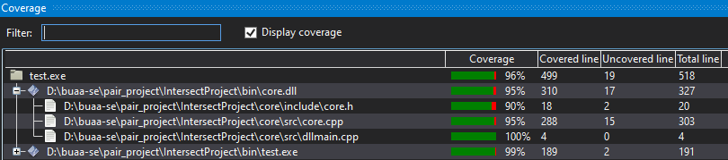
testing frame as follows
static int main_ret = 0;
static int test_count = 0;
static int test_pass = 0;

#define EXPECT_EQ_BASE(equality, expect, actual) \
    do {\
        test_count++;\
        if (equality)\
            test_pass++;\
        else {\
            std::cerr << __FILE__ << ":" << __LINE__ << ": expect: " << expect << " actual: " << actual << "\n"; \
            main_ret = 1;\
        }\
    } while(0)
#define EXPECT_EQ(expect, actual) EXPECT_EQ_BASE((expect) == (actual), expect, actual)
#define EXPECT_TRUE(actual) EXPECT_EQ_BASE((actual) != 0, "true", "false")
#define EXPECT_FALSE(actual) EXPECT_EQ_BASE((actual) == 0, "false", "true")

void gm_test()
{
    auto gm = create_graph_manager();
    ... // 测试项目
    dispose_graph_manager(gm);
}

int main()
{
    gm_test();
    printf("%d/%d (%3.2f%%) passed\n", test_pass, test_count, test_pass * 100.0 / test_count);
    return main_ret;
}
Test items are functional testing and test abnormalities.
First, functional testing, to test the two circle circumscribed circumstances, for example
clear_manager(gm);                              // 首先清空 GraghManager
add_circle(gm, nullptr, Type::circle, 0, 0, 1); // 加入一个圆,用空指针接收错误信息可以及时发现异常的发生
add_circle(gm, nullptr, Type::circle, 2, 0, 1); // 加入另一个圆
EXPECT_EQ(1, calculate_intersect(gm));          // 计算交点数并进行比较
Structure test data will be considered as well as in the case of plus or minus zero (-100 000 100000) in the vicinity of the data range, according to the classification of visible demand analysis.
Then the test is abnormal, as follows
// 两点重合
clear_manager(gm);
EXPECT_TRUE(add_line(gm, msg, Type::line_segment, 0, 0, 0, 0) > 0);
// 超出数据范围
clear_manager(gm);
EXPECT_TRUE(add_line(gm, msg, Type::line_segment, 10000000, 0, 0, 0) > 0);
// 超出数据范围
clear_manager(gm);
EXPECT_TRUE(add_line(gm, msg, Type::line_segment, 0, 0, 0, -10000000) > 0);
// 超出数据范围
clear_manager(gm);
EXPECT_TRUE(add_circle(gm, msg, Type::circle, 0, 0, -10000000) > 0);
// 半径为负
clear_manager(gm);
EXPECT_TRUE(add_circle(gm, msg, Type::circle, 0, 0, -1000) > 0);
// 计算交点前获取交点信息
clear_manager(gm);
EXPECT_TRUE(fetch_intersect(gm, msg, &x, &y) > 0);
// 无交点获取交点信息
calculate_intersect(gm, msg, &point_num);
EXPECT_TRUE(fetch_intersect(gm, msg, &x, &y) > 0);
// 输入数据中具有重合或重复的图形
add_circle(gm, nullptr, Type::circle, 0, 0, 3);
add_circle(gm, nullptr, Type::circle, 0, 0, 3);
EXPECT_TRUE(calculate_intersect(gm, msg, &point_num) > 0);
Interface Module Design
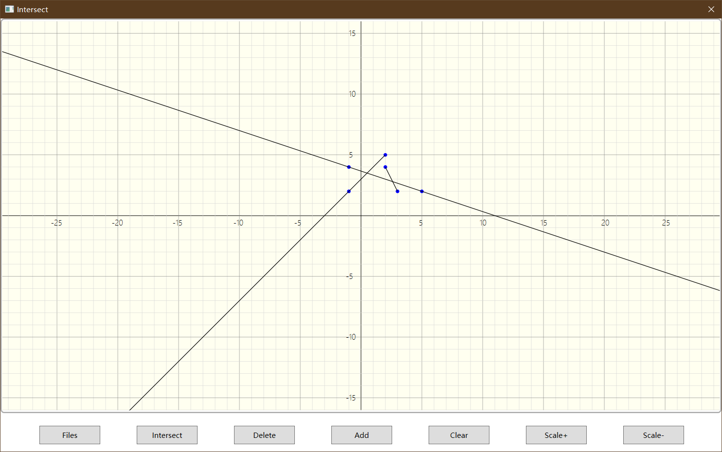
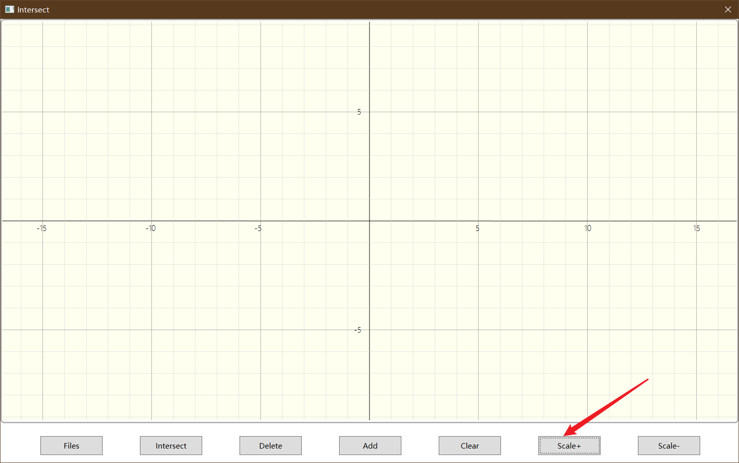
We selected interface module development framework is WPF, development language is C #. Since the interface module for the needs of the project given geometric object file import, additions and deletions, drawing and solving the intersection, these needs are available through a button click event is complete, it is the overall design of the interface module are: top with Sketchpad drawing showing content below arrangement button control. After completion of the initial interface is as follows:

Canvas Design
Canvas drawing a design drawing is divided into the coordinates of the grid geometry, the implementation details of the two is explained below.
Drawing axis is relatively simple, only two lines drawn in the center of the canvas, wherein both ends of the y-axis is the midpoint of the upper and lower boundaries of the canvas, both ends of the x-axis is the midpoint of the border around the canvas. The coordinates of the grid plotted in fact, only a coordinate axis plots enhanced version, is the staggered vertical and horizontal grid lines; coordinates by drawing TextBlockimplement. The following is a drawing showing the grid coordinates and the coordinates along the X-axis direction, y-axis can be inverted empathy.
Geometric objects drawn design
Drawing geometry into line drawing and drawing a circle, which is divided into an infinite line drawn straight line segments and rays.
Line drawing of the most troublesome, because the conventional method gives only the WPF framework supports drawing lines, infinite straight line is not supported. For us infinite lines and rays way to accomplish this is: add border points. The method of seeking the boundary point is: x is the abscissa INF_X order (here, half the width of the canvas take INF_X, i.e. the canvas into a boundary value at the center of the two-dimensional coordinate system) obtained by the linear equation y. Consider the case parallel to the axis, the code will not be repeated below:
// input: x1, y1, x2, y2
double A = y2 - y1, B = x1 - x2, C = x2 * y1 - x1 * y2;
double edge_x1, edge_x2, edge_y1, edge_y2;  // 1为边界起点,2为边界终点
double INFX = frame_width / 2;

if (x2 < x1)
{
    edge_x1 = INFX;
    edge_x2 = -INFX;
}
else
{
    edge_x1 = -INFX;
    edge_x2 = INFX;
}
edge_y1 = (-C - A * edge_x1) / B;
edge_y2 = (-C - A * edge_x2) / B;
After drawing can be carried out according to the type of line objects. Note that, prior to computing the two-dimensional coordinate system, when the last drawing canvas to convert coordinates to a coordinate system (two-dimensional coordinate system is taken along the x-axis of the fourth quadrant after inversion) to:
Point start;
Point end;
switch (type)
{
    case Type.infinite_line:    // 无限长直线
        start = convert_point(edge_x1, edge_y1);
        end = convert_point(edge_x2, edge_y2);
        break;
    case Type.line_segment:     // 射线
        start = convert_point(x1, y1);
        end = convert_point(edge_x2, edge_y2);
        break;
    case Type.segment: default:    // 线段
        start = convert_point(x1, y1);
        end = convert_point(x2, y2);
        break;
}

LineGeometry line = new LineGeometry();
line.StartPoint = start;
line.EndPoint = end;

Path path = new Path();
path.Stroke = Brushes.Black;
path.StrokeThickness = 1;
path.Data = line;

mainPanel.Children.Add(path);
convert_pointThe code is as follows:
private Point convert_point(double x, double y)
{
    return new Point(x * SCALE + x_offset, -y * SCALE + y_offset);
}
Circular coordinate point drawn may be provided using WPF EllipseGeometry(oval) class. Only the difference between both hollow and solid radial size, coordinate points drawing method is given below:
// input: x, y
Point p = convert_point(x, y);
EllipseGeometry el = new EllipseGeometry();
int pointR = 2;

el.RadiusX = pointR;
el.RadiusY = pointR;
el.Center = p;

Path path = new Path();
path.Stroke = Brushes.Black;
path.StrokeThickness = 2;
path.Fill = Brushes.Black;
path.Data = el;

mainPanel.Children.Add(path);
intersections.Add(path);
Button design
Button functions designed as follows:
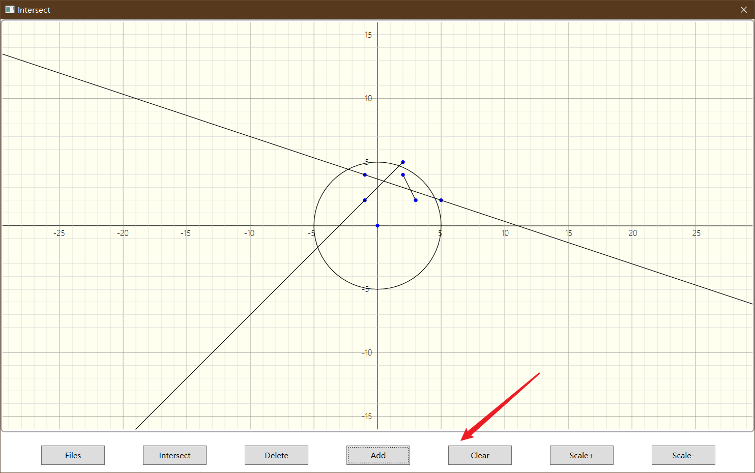
Files: Import describe geometric objects from the file and draw (not set "Draw" button in order to separate more intuitive display of geometric objects entered, the user clicks to avoid repeating redundant, add / delete button below also implement this idea).Intersect: Solving the intersection of existing geometry and draw objects.Delete: Select one of the geometric objects, remove it from the canvas, canvas and delete all the intersections .Add: Adding a geometry object according to the type and the selected input, and draw on the canvas.Clear: All intersection of geometric objects and the empty canvasScale+/-: Enlargement / reduction of the canvas coordinate system will delete all geometric object and intersection points on FIG.
The following shows the buttons to trigger the implementation details of the event.
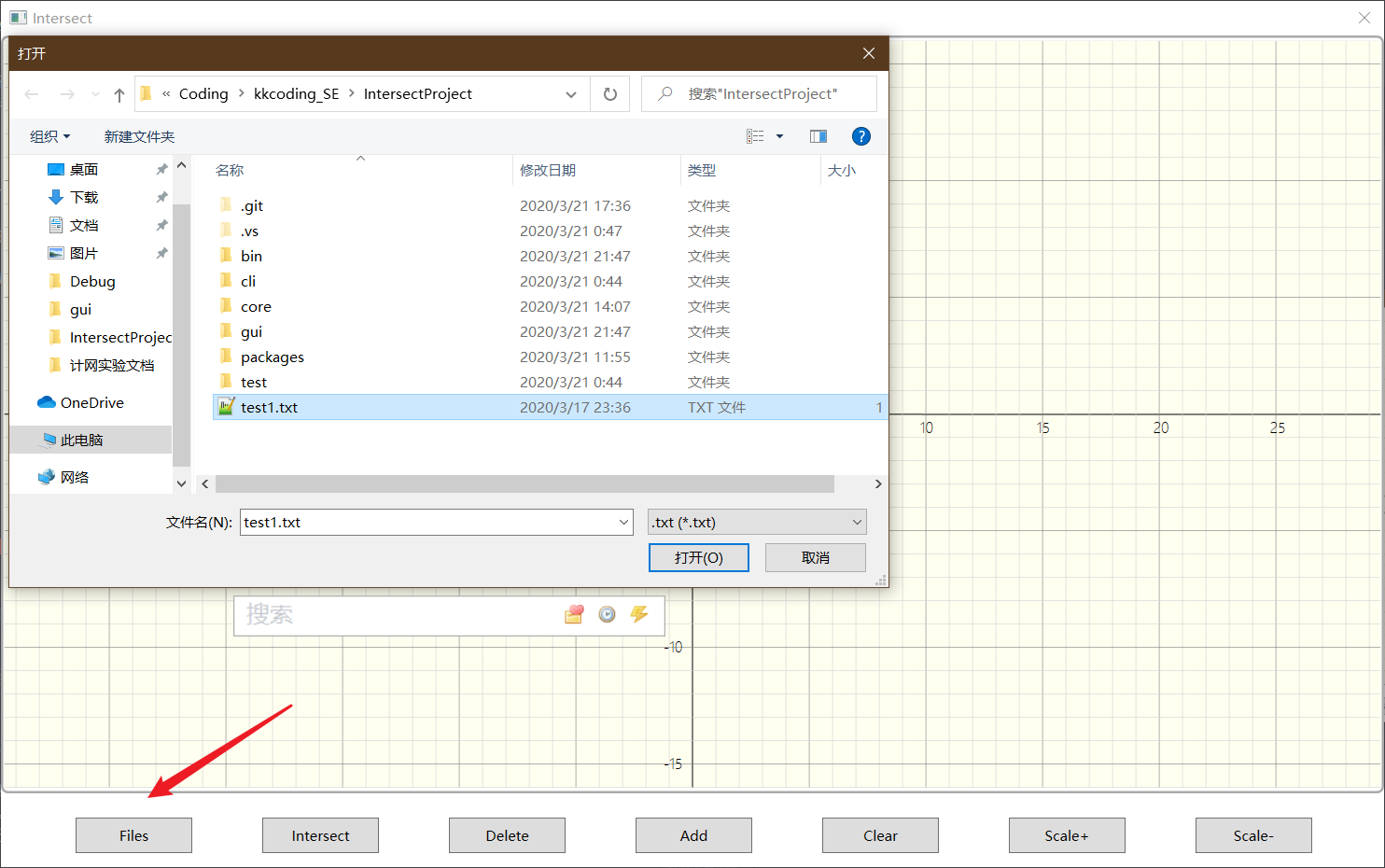
Wording button event function is:
-
Files
var dialog = new Microsoft.Win32.OpenFileDialog
{
    Filter = ".txt|*.txt"
};
if (dialog.ShowDialog(this) == false) return;
string fileName = dialog.FileName;

Console.WriteLine(fileName);

drawer.clearAll();      // 清除画布
drawer.DrawXY();        // 重新绘制坐标轴
drawer.ReadGraphFromFile(fileName);
Where the
read_graph_from_file()implementation flow method is as follows:- The first line read digital files
- Row read and parse the digital
- Geometric objects will parse the acquired information is input to the
corecalculation module to add - Calling line drawing method to draw
Which also involves a number of error determination, use
MessageBox.show()report errors -
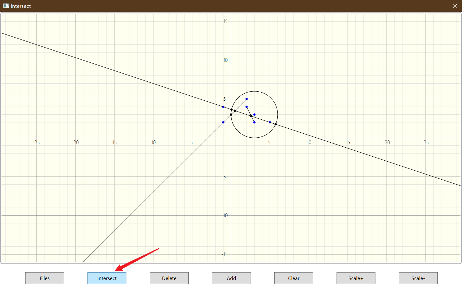
Intersect
The main event calls the
corecalculation module, and usecoretake the intersection of function implemented one by one to get all intersection.public void calc_and_draw_intersects() { // 计算交点 int r = NativeMethods.calculate_intersect(core_graph_manager, msg, ref n); if (r > 0) { MessageBox.Show(msg.ToString()); } for (long i = 0; i < n; i++) { // 从core中取一个交点坐标 r = NativeMethods.fetch_intersect(core_graph_manager, msg, ref x, ref y); if (r > 0) // 如果有错误信息 { MessageBox.Show(msg.ToString()); break; } else { drawIntersectPoint(x, y); } } } -
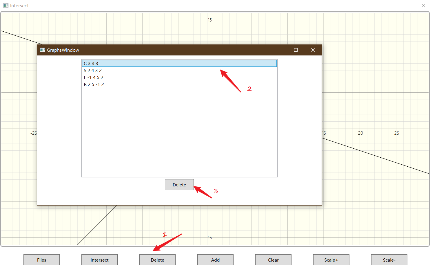
Delete
The event pops up a new window (projects for
GraphsWindow), get information of all geometric objects and use theListBoxdisplay, respectively delete it after the user to confirm the selectionListBoxdescription, canvas graphics as well ascoreobjects and remove all the intersections.Canvas delete a graphic logic is as follows:
// input: graph id // remove graoh on Canvas mainPanel.Children.Remove(graphs[id]); // remove info graphs.Remove(graphs[id]); // remove points on graph Path[] points = pointsOnGraph[id]; foreach (Path point in points) { mainPanel.Children.Remove(point); } pointsOnGraph.Remove(points); // remove intersections(all) foreach (Path intersect in intersections) { mainPanel.Children.Remove(intersect); } intersections.Clear(); // remove data in core remove_graph(core_graph_manager, id); -
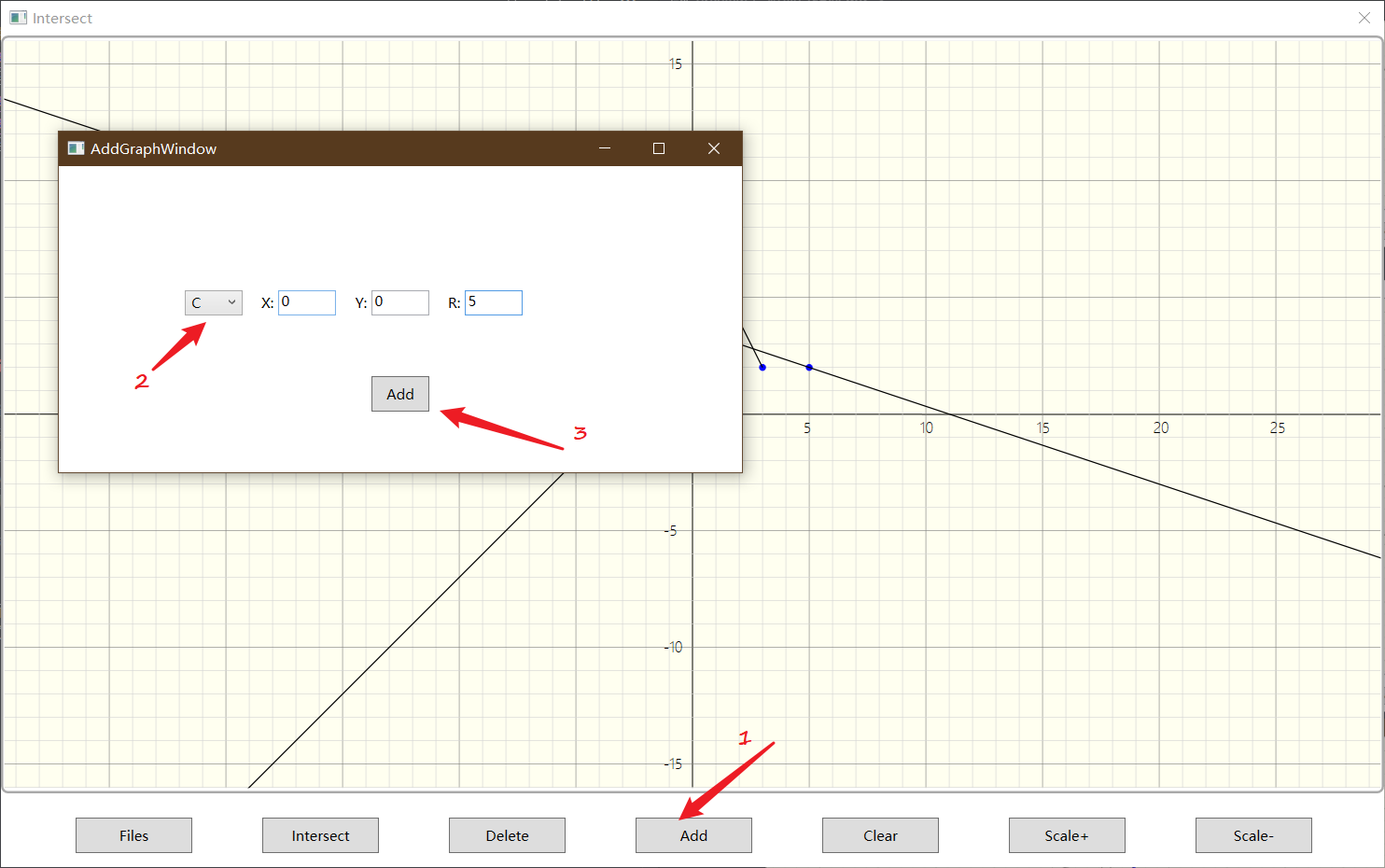
Add
The new pop-up window to add geometric objects. The method is implemented using
ComboBoxone of a choice of four implemented dropdown geometric object type, and gives a different number of parameters depending on the type of the input box (TextBox). The correctness of detection when submitting input. Finally, the correct input integrated into a line by line to add processing according to the method of processing the input file.string wrongMsg = ""; verify_TextInput(tbox1, tblock1, ref wrongMsg); verify_TextInput(tbox2, tblock2, ref wrongMsg); verify_TextInput(tbox3, tblock3, ref wrongMsg); if (combo.SelectedIndex != (int)ComboItem.C) // 圆形没有第四个参数输入框,只有x, y, r { verify_TextInput(tbox4, tblock4, ref wrongMsg); } if (wrongMsg.Length != 0) { MessageBox.Show(wrongMsg); // 输入栏的错误提醒 } else { string info = combo.Text + " " + tbox1.Text + " " + tbox2.Text + " " + tbox3.Text; if (combo.SelectedIndex != (int)ComboItem.C) { info += " " + tbox4.Text; } try { drawer.AddGraphFromLine(info); // 添加该行对应的几何对象信息 } catch (FormatException) { MessageBox.Show("Wrong Format!"); // 在执行添加逻辑时的错误报告 } } -
Clear
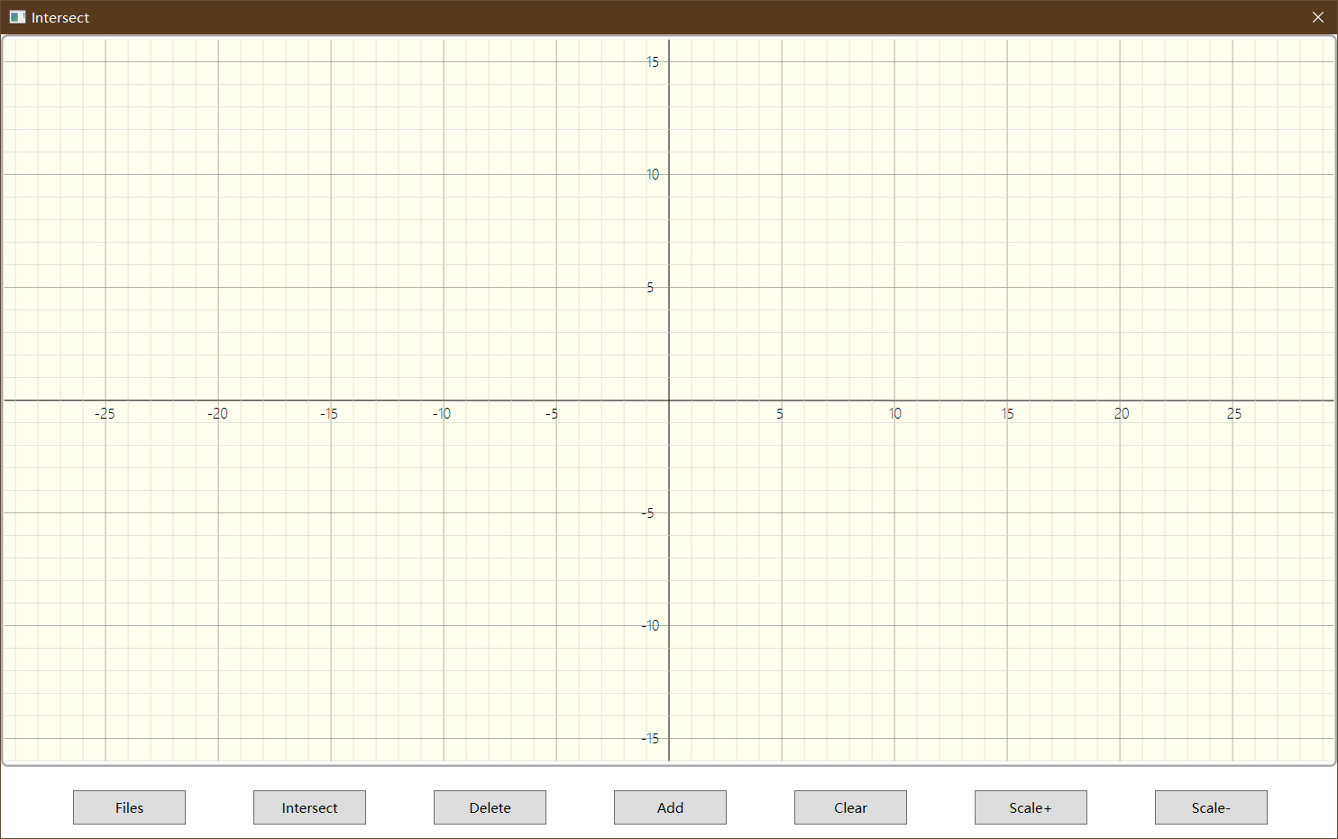
The event includes the clear contents of the canvas, all geometric object information, and re-painting coordinate grid. Clear the details are as follows:
mainPanel.Children.Clear(); // 清除画布内容 graphs.Clear(); // 清除几何对象绘制信息 intersections.Clear(); // 清除交点绘制信息 pointsOnGraph.Clear(); // 清除几何对象上的点(起点、终点、圆心)的绘制信息 graphsInfo.Clear(); // 清除用于生成ListBox的几何对象信息 core_graph_manager = IntPtr.Zero; // 清除core中的manager -
Scale + / -
The event by the size parameter to adjust the canvas
SCALEto achieve. Rendering coordinate grid, draw a vertical loop in the x-axis coordinates of the grid, the grid density is based onSCALEadjusted, thereby achieving increase or decrease the size of the canvas:for (int i = SCALE; i < frame_width / 2; i+=SCALE)In an implementation, the user clicks the button every Scale +/-, canvas first clearance,
SCALEincrease / decrease5, and set boundaries, avoid infinite amplification, then re-draw the axes.Logic implemented substantially as follows
if (SCALE >= 100)
{
    MessageBox.Show("Reach Max Scale", "Note");
    return;
}
clear_all();
SCALE += 5;
drawXY();
Docking module and the computing module interface
Calculation module generates a dynamic link library, since the interface module using C # WPF framework and development, can DLLImportbe introduced into the dll use statements interface.
Import interface module interface functions in the following statements:
[DllImport("core.dll")]
internal static extern IntPtr create_graph_manager();

[DllImport("core.dll", CallingConvention = CallingConvention.Cdecl, CharSet = CharSet.Ansi, BestFitMapping = false, ThrowOnUnmappableChar = true)]
internal static extern int add_line(IntPtr gm, StringBuilder msg, int type, long x1, long y1, long x2, long y2);

[DllImport("core.dll", CallingConvention = CallingConvention.Cdecl, CharSet = CharSet.Ansi, BestFitMapping = false, ThrowOnUnmappableChar = true)]
internal static extern int add_circle(IntPtr gm, StringBuilder msg, int type, long x, long y, long r);

[DllImport("core.dll", CallingConvention = CallingConvention.Cdecl, CharSet = CharSet.Ansi, BestFitMapping = false, ThrowOnUnmappableChar = true)]
internal static extern int calculate_intersect(IntPtr gm, StringBuilder msg, ref long res);

[DllImport("core.dll", CallingConvention = CallingConvention.Cdecl, CharSet = CharSet.Ansi, BestFitMapping = false, ThrowOnUnmappableChar = true)]
internal static extern int fetch_intersect(IntPtr gm, StringBuilder msg, ref double x, ref double y);

[DllImport("core.dll", CallingConvention = CallingConvention.Cdecl)]
internal static extern void remove_graph(IntPtr gm, long id);

[DllImport("core.dll", CallingConvention = CallingConvention.Cdecl)]
internal static extern void dispose_graph_manager(IntPtr gm);
In order to achieve conditions loosely coupled interface module is not involved in the operation class computing module. Each docking interfaces GraphManager pointer. We need to create a new GraphManager pointer initially:
IntPtr graph_manager = create_graph_manager();
After the addition of a line, depending on the type and the obtained input coordinates, a line can be added as follows:
add_Line(graph_manager, msg, type, x1, y1, x2, y2);
Wherein msg used to obtain error information calculating module through MessageBoxreported to the user.
Implement the following functions:
- Geometry information is read from the file and draw (Files button)
- Find the intersections and draw (Intersect button)
- Delete a geometry (Delete button)
- Add a geometry (Add button)

- Empty Canvas (Clear button)
- Increase or decrease the size of the canvas (will delete graphics)
- Scale + button
- Scale- button

- Scale + button
Code quality analysis
Screenshot below
Twinning process
Since the epidemic, we use voice chat and Live Share a way to pair programming. To be honest, the general effect, even we do not know each other. But the effect is still there, say, the variables are described coordinates x, y and the like, because I was not careful enough and often wrong variable names, if I programmed separately, these issues are likely to be postponed until the unit test if will be found, thanks to my teammates are more cautious, comparable to the clang-tidy, a timely reminder of my amendment.
This is actually a benefit to the junction of programming, while two pairs of eyes review the code. Also, because there are other people involved, will be forced to write their own code meaningful as possible, that is to say, make his teammates easily understand the intent of the code and understand the flow of execution.
The task there is a demand of graphical programming, which is I'm not good, and in this respect my teammates have a lot of help, when looking at the code also broadly understand the way WPF development.
PSP table
| PSP2.1 | Personal Software Process Stages | Estimated time consuming (minutes) | The actual time-consuming (minutes) |
|---|---|---|---|
| Planning | plan | ||
| · Estimate | • Estimate how much time this task requires | 5 | 15 |
| Development | Develop | ||
| · Analysis | · Needs analysis (including learning new technologies) | 60 | 120 |
| · Design Spec | Generate design documents | 30 | 30 |
| · Design Review | · Design Review (and his colleagues reviewed the design documents) | 30 | 30 |
| · Coding Standard | · Code specifications (development of appropriate norms for the current development) | 0 | 0 |
| · Design | · Specific design | 30 | 90 |
| · Coding | · Specific coding | 60 | 90 |
| · Code Review | · Code Review | 30 | 60 |
| · Test | · Test (self-test, modify the code, submit modifications) | 60 | 90 |
| Reporting | report | ||
| · Test Report | · testing report | 10 | 10 |
| · Size Measurement | · Computing workload | 10 | 10 |
| · Postmortem & Process Improvement Plan | · Hindsight, and propose process improvement plan | 30 | 30 |
| total | 355 | 575 |