纹理贴图
计算机图形学中的纹理既包括通常意义上物体表面的纹理即使物体表面呈现凹凸不平的沟纹,同时也包括在物体的光滑表面上的彩色图案,通常我们更多地称之为花纹。对于花纹而言,就是在物体表面绘出彩色花纹或图案,产生了纹理后的物体表面依然光滑如故。对于沟纹而言,实际上也是要在表面绘出彩色花纹或图案,同时要求视觉上给人以凹凸不平感即可。 凹凸不平的图案一般是不规则的。在计算机图形学中,这两种类型的纹理的生成方法完全一致, 这也是计算机图形学中把他们统称为纹理的原因所在。 所以纹理映射就是在物体的表面上绘制彩色的图案。
在三维图像世界中表示物体表面细节的一幅或几幅二维图形,也称纹理贴图(texture mapping),当把纹理按照特定的方式映射到物体表面上的时候能使物体看上去更加真实。纹理映射是一种允许我们为三角形赋予图像数据的技术,能够更细腻更真实地表现渲染场景。
在计算机图形学中,纹理贴图是使用图像、函数或其他数据源来改变物体表面外观的技术。
可以使用凹凸纹理在光滑的球上,呈现出凹凸不平的球的效果;

3D图形学(4):纹理贴图中详细介绍了3D图像学中纹理的生成原理,以及常用的几种纹理贴图方案;
《VTK图形图像开发进阶》中在2.2.4节讲到“其原理是渲染时把二维的图像贴到物体的表面上,根据二维图像渲染出丰富多彩的效果,所以纹理映射也被叫做纹理贴图”;纹理贴图的三个要素是:待贴图的表面、纹理映射以及纹理坐标(控制纹理图在面上的位置);
vtkTexture

vtkTexture是一种处理纹理贴图加载和与图像绑定的算法类,从输入图像数据集类型中获取数据。用户可以创建可视化管道来读取、处理和构造纹理。需要注意的是只有定义了纹理坐标并且渲染系统支持纹理时,纹理才会工作。
vtkTexture的实例通过actor的SetTexture()方法与actor关联。多个actor可以共享纹理贴图(节省内存资源)。
注意:
当前仅支持二维纹理贴图,即使数据管道支持1、2和三维纹理坐标。
一些渲染器(如旧的OpenGL)要求纹理贴图尺寸在每个方向上为2的幂。如果使用非二次幂纹理贴图,则会在一个或多个方向上自动将其重采样为二次幂,而代价是昂贵的计算。如果OpenGL实现足够新(OpenGL>=2.0或存在扩展GL_ARB_texture_non_power_of_two),则没有此类限制,也没有额外的计算成本。
接口
线性插值开关
用于控制在纹理映射时,是否进行线性插值;
vtkGetMacro(Interpolate, vtkTypeBool);
vtkSetMacro(Interpolate, vtkTypeBool);
vtkBooleanMacro(Interpolate, vtkTypeBool);
mipmap开关
MIP map(有时候拼写成mipmap)是一种电脑图形图像技术,用于在三维图像的二维代替物中达到立体感效应。MIP map技术与材质贴图技术结合,根据距观看者远近距离的不同,以不同的分辨率将单一的材质贴图以多重图像的形式表现出来并代表平面纹理:尺寸最大的图像放在前面显著的位置,而相对较小的图像则后退到背景区域。每一个不同的尺寸等级定义成一个MIP map水平。MIP map技术帮助避免了不想要的锯齿边缘(称为锯齿状图形)在图像中出现,这种锯齿状图形可能是由于在不同分辨率下使用bit map图像产生的。
vtkGetMacro(Mipmap, bool);
vtkSetMacro(Mipmap, bool);
vtkBooleanMacro(Mipmap, bool);
示例
墙角
具体步骤:
1.读入一张jpeg的二维图像作为纹理图textureFile;
2.定义一个纹理vtkTexture类的对象atext,将textureFile的输出放入atext的输入中,作为它即将贴到平面上的一个纹理图;
3.定义一个vtkPlaneSource对象plane,类vtkPlaneSource可以生成一个平面,也就是纹理图要贴图的地方。
4.定义一个vtkActor对象planeActor,将plane对应的vtkPolyDataMapper设置到其中,通过SetTexture方法设定atext为该演员的纹理;
vtkNew<vtkImageReader2Factory> readerFactory;
vtkSmartPointer<vtkImageReader2> textureFile;
textureFile.TakeReference(readerFactory->CreateImageReader2("G:\\Data\\texture.jpg"));
textureFile->SetFileName("G:\\Data\\texture.jpg");
textureFile->Update();

vtkNew<vtkTexture> atext;
atext->SetInputConnection(textureFile->GetOutputPort());
atext->InterpolateOn();

// Create a plane source and actor. The vtkPlanesSource generates
// texture coordinates.
vtkNew<vtkPlaneSource> plane;

vtkNew<vtkPolyDataMapper> planeMapper;
planeMapper->SetInputConnection(plane->GetOutputPort());

vtkNew<vtkActor> planeActor;
planeActor->SetMapper(planeMapper);
planeActor->SetTexture(atext);

// Create the RenderWindow, Renderer and both Actors
vtkNew<vtkNamedColors> colors;
vtkNew<vtkRenderer> renderer;

vtkNew<vtkRenderWindow> renWin;
renWin->AddRenderer(renderer);

vtkNew<vtkRenderWindowInteractor> iren;
iren->SetRenderWindow(renWin);

// Add the actors to the renderer, set the background and size
renderer->AddActor(planeActor);
renderer->SetBackground(colors->GetColor3d("DarkSlateGray").GetData());
renWin->SetSize(640, 480);
renWin->SetWindowName("TexturePlane");

// render the image
renWin->Render();

renderer->ResetCamera();
renderer->GetActiveCamera()->Elevation(-30);
renderer->GetActiveCamera()->Roll(-20);
renderer->ResetCameraClippingRange();
renWin->Render();
iren->Start();


vtkPlaneSource在创建平面的同时自动产生了纹理坐标,可以用下面的代码将坐标输出;可以看到plane平面的坐标和实际坐标的对应关系;
    vtkNew<vtkPlaneSource> plane;
    plane->Update();
    double a[3] = {

     0 };
    cout << "Points:" << plane->GetOutput()->GetNumberOfPoints() << endl;
    vtkDataArray* tcoord = plane->GetOutput()->GetPointData()->GetTCoords();
    for (size_t i = 0; i < tcoord->GetNumberOfTuples(); i++) {


        cout << "Point " << i << " in texture:(";
        for (size_t j = 0; j < tcoord->GetNumberOfComponents(); j++) {


            cout << tcoord->GetComponent(i, j) << ",";
        }
        cout<<");" << endl;
    }

    for (size_t i = 0; i < plane->GetOutput()->GetNumberOfPoints(); i++) {


        plane->GetOutput()->GetPoint(i, a);
        cout << "plane " << i << " in Position:(" << a[0] << "," << a[1] <<");"<< endl;
    }
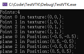
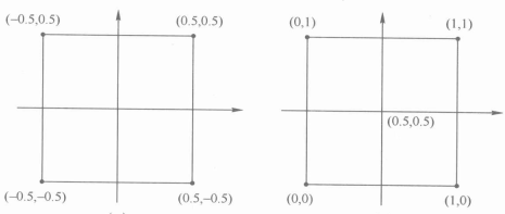
下图的左侧是四个点的空间坐标,右侧是对应点的纹理坐标。
进行纹理映射时,就是根据归一化的纹理坐标,在纹理贴图上寻找相应的颜色属性,并将其应用在平面上;
除了上文的平铺贴图,还可以对纹理坐标进行缩放,使纹理贴图在物体表面循环出现,类似于Windows桌面壁纸的平铺效果。
纹理坐标的变换操作由vtkTransformTextureCoords实现,需要将其插入到映射器的流水线中;
改写代码,平铺两张纹理图:
    vtkNew<vtkPlaneSource> plane;
    plane->SetResolution(2, 2);
    plane->Update();

    vtkNew<vtkTransformTextureCoords> xform;
    xform->SetInputConnection(plane->GetOutputPort());
    xform->SetScale(2, 1, 1);
    xform->Update();

    double a[3] = {

     0 };
    cout << "Points:" << xform->GetOutput()->GetNumberOfPoints() << endl;
    vtkDataArray* tcoord = xform->GetOutput()->GetPointData()->GetTCoords();
    for (size_t i = 0; i < tcoord->GetNumberOfTuples(); i++) {


        cout << "Point " << i << " in texture:(";
        for (size_t j = 0; j < tcoord->GetNumberOfComponents(); j++) {


            cout << tcoord->GetComponent(i, j) << ",";
        }
        cout<<");" << endl;
    }

    for (size_t i = 0; i < xform->GetOutput()->GetNumberOfPoints(); i++) {


        xform->GetOutput()->GetPoint(i, a);
        cout << "plane " << i << " in Position:(" << a[0] << "," << a[1] <<");"<< endl;
    }

    vtkNew<vtkPolyDataMapper> planeMapper;
    planeMapper->SetInputConnection(xform->GetOutputPort());
使用方法SetScale()来对纹理坐标进行缩放,方法的三个参数分别表示的是对应纹理坐标的三个分量的缩放值。
xform->SetScale(2, 1, 1);表示了在x方向上缩放2倍,即从中心开始到两侧,每个点在x方向上相对于中心的间距变为原来的两倍;
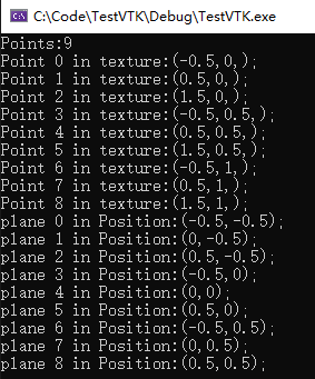
从上图可以,获知相对坐标位置和纹理坐标位置;计算得到下图:
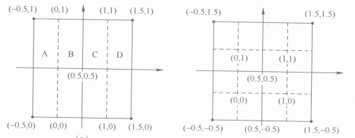
由于纹理坐标超出了0-1的范围,所以要将纹理坐标理解为是以1位周期对应到贴图上相应位置的。
对于上图中的B区和C区,其纹理坐标还在范围之内,并且构成一个完整的贴图区域,因此一张完整的贴图可以贴在这里,只是在y方向上拉伸了;对于A区和D区,就需要将纹理坐标理解为以1为周期对应的贴图上的相应位置上,即坐标加减1个单位后,对应的贴图区域是相等的。A区中每个点纹理坐标的x分量加1,就跟C区一样了,给D区中的每个点纹理坐标x分量减1,就跟B区一样了,之后进行贴图映射时,A区和D区贴上的图就分别与C区和B区相同了。

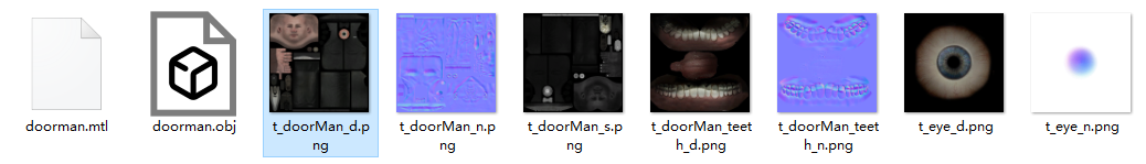
doorman
vtkNew<vtkOBJImporter> importer;
importer->SetFileName("G:\\Data\\doorman\\doorman.obj");
importer->SetFileNameMTL("G:\\Data\\doorman\\doorman.mtl");
importer->SetTexturePath("G:\\Data\\doorman\\");

vtkNew<vtkNamedColors> colors;
vtkNew<vtkRenderer> renderer;
vtkNew<vtkRenderWindow> renWin;
vtkNew<vtkRenderWindowInteractor> iren;

renderer->SetBackground2(colors->GetColor3d("Silver").GetData());
renderer->SetBackground(colors->GetColor3d("Gold").GetData());
renderer->GradientBackgroundOn();
renWin->AddRenderer(renderer);
renderer->UseHiddenLineRemovalOn();
renWin->AddRenderer(renderer);
renWin->SetSize(640, 480);
renWin->SetWindowName("OBJImporter");

iren->SetRenderWindow(renWin);
importer->SetRenderWindow(renWin);
importer->Update();

auto actors = renderer->GetActors();
actors->InitTraversal();
std::cout << "There are " << actors->GetNumberOfItems() << " actors" << std::endl;

for (vtkIdType a = 0; a < actors->GetNumberOfItems(); ++a) {


	std::cout << importer->GetOutputDescription(a) << std::endl;
	vtkActor* actor = actors->GetNextActor();
	// OBJImporter turns texture interpolation off
	if (actor->GetTexture()) {


		std::cout << "Has texture\n";
		actor->GetTexture()->InterpolateOn();
	}

	vtkPolyData* pd = dynamic_cast<vtkPolyData*>(actor->GetMapper()->GetInput());
	vtkPolyDataMapper* mapper = dynamic_cast<vtkPolyDataMapper*>(actor->GetMapper());
	mapper->SetInputData(pd);
}
renWin->Render();
iren->Start();


参考资料
1.纹理
2.3D图形学(4):纹理贴图
3.TexturePlane
4.Mipmap
5.医学图像编程技术