Basado en la producción de reloj electrónico RASC keil, tubo digital LED de 5 unidades
descripción general
Este artículo presenta principalmente cómo usar e2studio para controlar el tubo digital de la placa de desarrollo Renesas RA2E1.
preparación de hardware
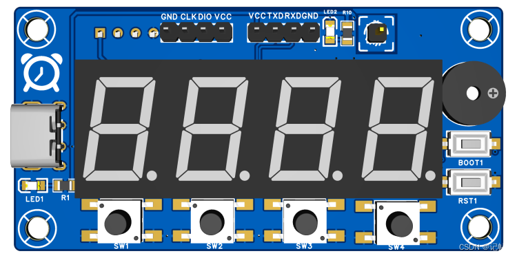
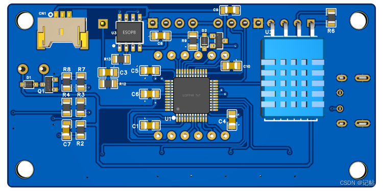
Primero, debe preparar una placa de desarrollo. Aquí estoy preparando una placa de desarrollo con el modelo de chip R7FA2E1A72DFL:
videotutorial
https://www.bilibili.com/video/BV1Bx4y197iy/
Producción de reloj electrónico Keil basada en RASC (Renesas RA)----(5) tubo digital LED de accionamiento
Descripción del tubo digital
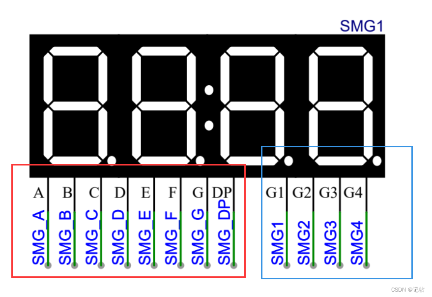
Puede saber por el manual que el tubo digital es un cátodo común.
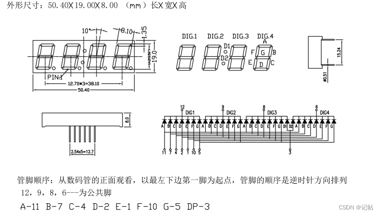
Verifique el diagrama esquemático al mismo tiempo, puede ver que el tubo digital está conectado al pin correspondiente de la MCU.
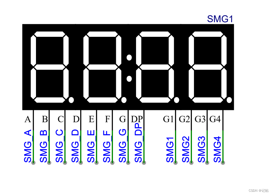
Configure estos IO como puertos de salida. Cuando el rojo es alto y el azul es bajo, el LED está encendido.
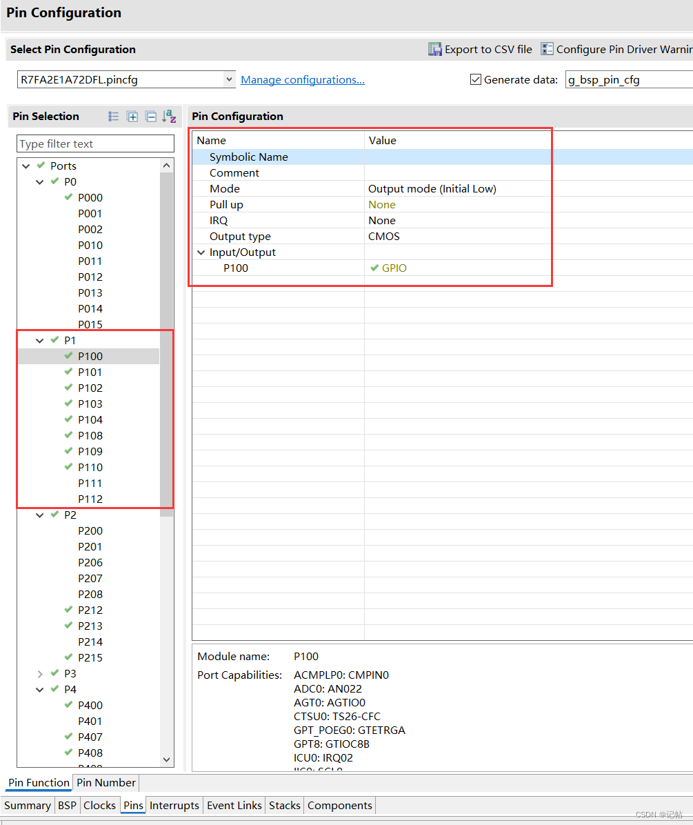
Configurar el puerto IO
Configure las E/S conectadas a los tubos digitales como modo de salida (inicial bajo).
Biblioteca de visualización de tubos Nixie
El control y enseñanza del tubo digital es el siguiente.
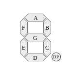
La siguiente figura enumera los segmentos que se iluminan cuando el tubo nixie muestra 0 a F. Por ejemplo, cuando se muestra el número 0, se iluminan todos los segmentos excepto el segmento G en el medio. El número 1 solo ilumina el segmento B y el segmento C.
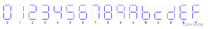
El proyecto aquí es un reloj electrónico, por lo que las fuentes que se utilizarán son 0-9. La biblioteca de fuentes de temperatura y humedad se agregará más adelante.
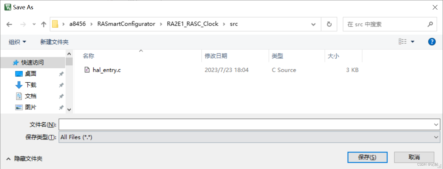
Cree nuevos archivos smg.c y smg.h para guardar el controlador del tubo digital.
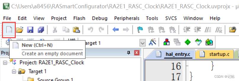
Guárdelos en la carpeta SRC.
smg.c
/*
 * smg.c
 *
 *  Created on: 2023年6月29日
 *      Author: a8456
 */

#include "smg.h"
#include "hal_data.h"


void smg_num(int num)
{


    switch(num)
    {


        case 0:
        {


            SMG_A_OPEN;
            SMG_B_OPEN;
            SMG_C_OPEN;
            SMG_D_OPEN;
            SMG_E_OPEN;
            SMG_F_OPEN;
            SMG_G_CLOSE;
            SMG_DP_CLOSE;
            break;
        }
        case 1:
        {


            SMG_A_CLOSE;
            SMG_B_OPEN;
            SMG_C_OPEN;
            SMG_D_CLOSE;
            SMG_E_CLOSE;
            SMG_F_CLOSE;
            SMG_G_CLOSE;
            SMG_DP_CLOSE;
            break;
        }
        case 2:
        {


            SMG_A_OPEN;
            SMG_B_OPEN;
            SMG_C_CLOSE;
            SMG_D_OPEN;
            SMG_E_OPEN;
            SMG_F_CLOSE;
            SMG_G_OPEN;
            SMG_DP_CLOSE;
            break;
        }
        case 3:
        {


            SMG_A_OPEN;
            SMG_B_OPEN;
            SMG_C_OPEN;
            SMG_D_OPEN;
            SMG_E_CLOSE;
            SMG_F_CLOSE;
            SMG_G_OPEN;
            SMG_DP_CLOSE;
            break;
        }
        case 4:
        {


            SMG_A_CLOSE;
            SMG_B_OPEN;
            SMG_C_OPEN;
            SMG_D_CLOSE;
            SMG_E_CLOSE;
            SMG_F_OPEN;
            SMG_G_OPEN;
            SMG_DP_CLOSE;
            break;
        }
        case 5:
        {


            SMG_A_OPEN;
            SMG_B_CLOSE;
            SMG_C_OPEN;
            SMG_D_OPEN;
            SMG_E_CLOSE;
            SMG_F_OPEN;
            SMG_G_OPEN;
            SMG_DP_CLOSE;
            break;
        }
        case 6:
        {


            SMG_A_OPEN;
            SMG_B_CLOSE;
            SMG_C_OPEN;
            SMG_D_OPEN;
            SMG_E_OPEN;
            SMG_F_OPEN;
            SMG_G_OPEN;
            SMG_DP_CLOSE;
            break;
        }
        case 7:
        {


            SMG_A_OPEN;
            SMG_B_OPEN;
            SMG_C_OPEN;
            SMG_D_CLOSE;
            SMG_E_CLOSE;
            SMG_F_CLOSE;
            SMG_G_CLOSE;
            SMG_DP_CLOSE;
            break;
        }
        case 8:
        {


            SMG_A_OPEN;
            SMG_B_OPEN;
            SMG_C_OPEN;
            SMG_D_OPEN;
            SMG_E_OPEN;
            SMG_F_OPEN;
            SMG_G_OPEN;
            SMG_DP_CLOSE;
            break;
        }
        case 9:
        {


            SMG_A_OPEN;
            SMG_B_OPEN;
            SMG_C_OPEN;
            SMG_D_OPEN;
            SMG_E_CLOSE;
            SMG_F_OPEN;
            SMG_G_OPEN;
            SMG_DP_CLOSE;
            break;
        }


    }


}

void smg_1(int num)
{


    SMG_1_OPEN;
    SMG_2_CLOSE;
    SMG_3_CLOSE;
    SMG_4_CLOSE;

    smg_num(num);

}


void smg_2(int num)
{


    SMG_1_CLOSE;
    SMG_2_OPEN;
    SMG_3_CLOSE;
    SMG_4_CLOSE;
    smg_num(num);

}


void smg_3(int num)
{


    SMG_1_CLOSE;
    SMG_2_CLOSE;
    SMG_3_OPEN;
    SMG_4_CLOSE;
    smg_num(num);

}


void smg_4(int num)
{


    SMG_1_CLOSE;
    SMG_2_CLOSE;
    SMG_3_CLOSE;
    SMG_4_OPEN;
    smg_num(num);

}


void smg_1_p(void)
{


    SMG_1_OPEN;
    SMG_2_CLOSE;
    SMG_3_CLOSE;
    SMG_4_CLOSE;

    SMG_A_OPEN;
    SMG_B_OPEN;
    SMG_C_CLOSE;
    SMG_D_CLOSE;
    SMG_E_OPEN;
    SMG_F_OPEN;
    SMG_G_OPEN;
    SMG_DP_CLOSE;

}


void smg_1_close(void)
{


    SMG_1_OPEN;
    SMG_2_CLOSE;
    SMG_3_CLOSE;
    SMG_4_CLOSE;

    SMG_A_CLOSE;
    SMG_B_CLOSE;
    SMG_C_CLOSE;
    SMG_D_CLOSE;
    SMG_E_CLOSE;
    SMG_F_CLOSE;
    SMG_G_CLOSE;
    SMG_DP_CLOSE;

}


void smg_2_close(void)
{


    SMG_1_CLOSE;
    SMG_2_OPEN;
    SMG_3_CLOSE;
    SMG_4_CLOSE;

    SMG_A_CLOSE;
    SMG_B_CLOSE;
    SMG_C_CLOSE;
    SMG_D_CLOSE;
    SMG_E_CLOSE;
    SMG_F_CLOSE;
    SMG_G_CLOSE;
    SMG_DP_CLOSE;
}


void smg_3_close(void)
{


    SMG_1_CLOSE;
    SMG_2_CLOSE;
    SMG_3_OPEN;
    SMG_4_CLOSE;

    SMG_A_CLOSE;
    SMG_B_CLOSE;
    SMG_C_CLOSE;
    SMG_D_CLOSE;
    SMG_E_CLOSE;
    SMG_F_CLOSE;
    SMG_G_CLOSE;
    SMG_DP_CLOSE;
}


void smg_4_close(void)
{


    SMG_1_CLOSE;
    SMG_2_CLOSE;
    SMG_3_CLOSE;
    SMG_4_OPEN;

    SMG_A_CLOSE;
    SMG_B_CLOSE;
    SMG_C_CLOSE;
    SMG_D_CLOSE;
    SMG_E_CLOSE;
    SMG_F_CLOSE;
    SMG_G_CLOSE;
    SMG_DP_CLOSE;
}


void smg_maohao_open(int num)
{


    SMG_1_CLOSE;
    SMG_2_CLOSE;

    if(num)//开启冒号
    {


        SMG_3_OPEN;
        SMG_4_OPEN;
        SMG_A_CLOSE;
        SMG_B_CLOSE;
        SMG_C_CLOSE;
        SMG_D_CLOSE;
        SMG_E_CLOSE;
        SMG_F_CLOSE;
        SMG_G_CLOSE;
        SMG_DP_OPEN;


    }
    else
    {


        SMG_3_CLOSE;
        SMG_4_CLOSE;

        SMG_A_CLOSE;
        SMG_B_CLOSE;
        SMG_C_CLOSE;
        SMG_D_CLOSE;
        SMG_E_CLOSE;
        SMG_F_CLOSE;
        SMG_G_CLOSE;
        SMG_DP_CLOSE;

    }
}

void ceshi_smg(void)
{


    for(int i=0;i<40;i++)
    {


        if(i<10)
        {

       smg_1(i);}

        else if(i>=10&&i<20)
        {

        smg_2(i-10);}

        else if(i>=20&&i<30)
        {

        smg_3(i-20);}

        else if(i>=30&&i<40)
        {

       smg_4(i-30);}


        R_BSP_SoftwareDelay(100U, BSP_DELAY_UNITS_MILLISECONDS);
    }
     smg_maohao_open(1);


}
smg.h
/*aa
 *
 *  Created on: 2023年6月29日
 *      Author: a8456
 */

#ifndef SMG_H_
#define SMG_H_
#define SMG_A_OPEN  R_IOPORT_PinWrite(&g_ioport_ctrl, BSP_IO_PORT_01_PIN_03, BSP_IO_LEVEL_HIGH)
#define SMG_B_OPEN  R_IOPORT_PinWrite(&g_ioport_ctrl, BSP_IO_PORT_05_PIN_00, BSP_IO_LEVEL_HIGH)
#define SMG_C_OPEN  R_IOPORT_PinWrite(&g_ioport_ctrl, BSP_IO_PORT_02_PIN_13, BSP_IO_LEVEL_HIGH)
#define SMG_D_OPEN  R_IOPORT_PinWrite(&g_ioport_ctrl, BSP_IO_PORT_04_PIN_08, BSP_IO_LEVEL_HIGH)
#define SMG_E_OPEN  R_IOPORT_PinWrite(&g_ioport_ctrl, BSP_IO_PORT_04_PIN_07, BSP_IO_LEVEL_HIGH)
#define SMG_F_OPEN  R_IOPORT_PinWrite(&g_ioport_ctrl, BSP_IO_PORT_01_PIN_02, BSP_IO_LEVEL_HIGH)
//旧版PCB
//#define SMG_G_OPEN  R_IOPORT_PinWrite(&g_ioport_ctrl, BSP_IO_PORT_04_PIN_00, BSP_IO_LEVEL_HIGH)
//新版PCB
#define SMG_G_OPEN  R_IOPORT_PinWrite(&g_ioport_ctrl, BSP_IO_PORT_00_PIN_00, BSP_IO_LEVEL_HIGH)
#define SMG_DP_OPEN R_IOPORT_PinWrite(&g_ioport_ctrl, BSP_IO_PORT_02_PIN_12, BSP_IO_LEVEL_HIGH)


#define SMG_A_CLOSE R_IOPORT_PinWrite(&g_ioport_ctrl, BSP_IO_PORT_01_PIN_03, BSP_IO_LEVEL_LOW)
#define SMG_B_CLOSE R_IOPORT_PinWrite(&g_ioport_ctrl, BSP_IO_PORT_05_PIN_00, BSP_IO_LEVEL_LOW)
#define SMG_C_CLOSE R_IOPORT_PinWrite(&g_ioport_ctrl, BSP_IO_PORT_02_PIN_13, BSP_IO_LEVEL_LOW)
#define SMG_D_CLOSE R_IOPORT_PinWrite(&g_ioport_ctrl, BSP_IO_PORT_04_PIN_08, BSP_IO_LEVEL_LOW)
#define SMG_E_CLOSE R_IOPORT_PinWrite(&g_ioport_ctrl, BSP_IO_PORT_04_PIN_07, BSP_IO_LEVEL_LOW)
#define SMG_F_CLOSE R_IOPORT_PinWrite(&g_ioport_ctrl, BSP_IO_PORT_01_PIN_02, BSP_IO_LEVEL_LOW)
//旧版PCB
//#define SMG_G_CLOSE R_IOPORT_PinWrite(&g_ioport_ctrl, BSP_IO_PORT_04_PIN_00, BSP_IO_LEVEL_LOW)
//新版PCB
#define SMG_G_CLOSE R_IOPORT_PinWrite(&g_ioport_ctrl, BSP_IO_PORT_00_PIN_00, BSP_IO_LEVEL_LOW)
#define SMG_DP_CLOSE R_IOPORT_PinWrite(&g_ioport_ctrl, BSP_IO_PORT_02_PIN_12, BSP_IO_LEVEL_LOW)

#define SMG_1_OPEN R_IOPORT_PinWrite(&g_ioport_ctrl, BSP_IO_PORT_01_PIN_04, BSP_IO_LEVEL_LOW)
#define SMG_2_OPEN R_IOPORT_PinWrite(&g_ioport_ctrl, BSP_IO_PORT_01_PIN_01, BSP_IO_LEVEL_LOW)
#define SMG_3_OPEN R_IOPORT_PinWrite(&g_ioport_ctrl, BSP_IO_PORT_01_PIN_00, BSP_IO_LEVEL_LOW)
//旧版PCB
//#define SMG_4_OPEN R_IOPORT_PinWrite(&g_ioport_ctrl, BSP_IO_PORT_00_PIN_00, BSP_IO_LEVEL_LOW)
//新版PCB
#define SMG_4_OPEN R_IOPORT_PinWrite(&g_ioport_ctrl, BSP_IO_PORT_04_PIN_00, BSP_IO_LEVEL_LOW)


#define SMG_1_CLOSE R_IOPORT_PinWrite(&g_ioport_ctrl, BSP_IO_PORT_01_PIN_04, BSP_IO_LEVEL_HIGH)
#define SMG_2_CLOSE R_IOPORT_PinWrite(&g_ioport_ctrl, BSP_IO_PORT_01_PIN_01, BSP_IO_LEVEL_HIGH)
#define SMG_3_CLOSE R_IOPORT_PinWrite(&g_ioport_ctrl, BSP_IO_PORT_01_PIN_00, BSP_IO_LEVEL_HIGH)
//旧版PCB
//#define SMG_4_CLOSE R_IOPORT_PinWrite(&g_ioport_ctrl, BSP_IO_PORT_00_PIN_00, BSP_IO_LEVEL_HIGH)
//新版PCB
#define SMG_4_CLOSE R_IOPORT_PinWrite(&g_ioport_ctrl, BSP_IO_PORT_04_PIN_00, BSP_IO_LEVEL_HIGH)


void smg_num(int num);

void smg_1(int num);
void smg_2(int num);
void smg_3(int num);
void smg_4(int num);

void smg_1_p(void);


void smg_1_close(void);
void smg_2_close(void);
void smg_3_close(void);
void smg_4_close(void);
void smg_maohao_open(int num);

void ceshi_smg(void);
#endif /* SMG_H_ */
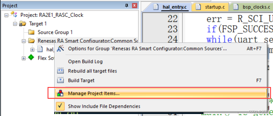
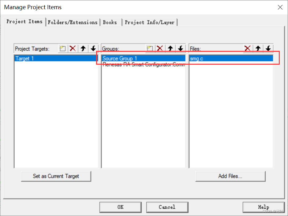
Importe el archivo ahora mismo.
Después de agregar, debe agregar el archivo de encabezado correspondiente al programa principal.
#include "smg.h"
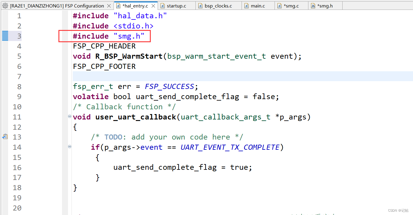
Agregar un programa de prueba.

programa principal
#include "hal_data.h"
#include <stdio.h>
#include "smg.h"
FSP_CPP_HEADER
void R_BSP_WarmStart(bsp_warm_start_event_t event);
FSP_CPP_FOOTER

fsp_err_t err = FSP_SUCCESS;
volatile bool uart_send_complete_flag = false;
/* Callback function */
void user_uart_callback(uart_callback_args_t *p_args)
{


    /* TODO: add your own code here */
    if(p_args->event == UART_EVENT_TX_COMPLETE)
     {


         uart_send_complete_flag = true;
     }
}


#ifdef __GNUC__                                 //串口重定向
    #define PUTCHAR_PROTOTYPE int __io_putchar(int ch)
#else
    #define PUTCHAR_PROTOTYPE int fputc(int ch, FILE *f)
#endif

PUTCHAR_PROTOTYPE
{


        err = R_SCI_UART_Write(&g_uart9_ctrl, (uint8_t *)&ch, 1);
        if(FSP_SUCCESS != err) __BKPT();
        while(uart_send_complete_flag == false){

    }
        uart_send_complete_flag = false;
        return ch;
}

int _write(int fd,char *pBuffer,int size)
{


    for(int i=0;i<size;i++)
    {


        __io_putchar(*pBuffer++);
    }
    return size;
}


/*******************************************************************************************************************//**
 * main() is generated by the RA Configuration editor and is used to generate threads if an RTOS is used.  This function
 * is called by main() when no RTOS is used.
 **********************************************************************************************************************/
void hal_entry(void)
{


    /* TODO: add your own code here */

/**********************串口设置***************************************/
    /* Open the transfer instance with initial configuration. */
       err = R_SCI_UART_Open(&g_uart9_ctrl, &g_uart9_cfg);
       assert(FSP_SUCCESS == err);

/**********************数码管测试***************************************/
       ceshi_smg();

       while(1)
       {


       printf("hello world!\n");
       R_BSP_SoftwareDelay(1000U, BSP_DELAY_UNITS_MILLISECONDS);
       }


#if BSP_TZ_SECURE_BUILD
    /* Enter non-secure code */
    R_BSP_NonSecureEnter();
#endif
}
Únase al programa de prueba para el tubo digital.