STM32 transplant to GD32
First, the Migration Notes
Recently, a project to replace the original STM32 want to use GD, GD because of lower costs. Then I find information on some of the GD and found some online currently available data are relatively old, such as GD ST transplanted to the Raiders, many of them stay in the GD just to promote the transition period soon, now no longer applies. Some of that was the official chip GD also developed a corresponding pack bag or firmware library, then transplant GD can only choose STM32 chip inside the project, and then modify the firmware libraries 32. And now, GD chips have their own libraries and firmware pack package, just install the corresponding pack package can choose corresponding GD chip in the chip selection there. So if you are doing a new project with GD, you can use GD official demo development, eliminating the need to program 32 into the GD. But for me this program has been commissioning original 32, only modified to be able to use GD people, 32 by modifying the firmware is compatible with GD library to be most convenient.
Before I made a blog post talking about the difference between the STM32 and GD32, there is not much talk about it. STM32 and GD32 model is one to one, like my test STM32F103C8T6 and GD32F103C8T6, pinout used is exactly the same, when the test I was directly above the board STM32 removed to replace the GD32. Translation software is used keil, after a time, then I will write another IAR's.
Well, ado, here immediately began to explain the process of transplantation, transplant all the files used in the process I will upload package, please download link at the bottom of the article.
Second, the migration steps
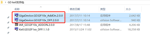
1, install GD support package.
GD program the chip can choose to replace the STM32, but burn when Flash must choose GD, so installation support package is a must. Pack package I installed older version, but could not find the latest in keil official website, so first make do with. Open the two files Figure 1, attached to the installation directory keil on it.
Note: I saw some former Raiders are doing this: The first step: decompression GD32F10xxx Keil IDE Config.rar compressed files. Step two: programming algorithm file FLM file copied to the installation path of MDK "\ Keil \ ARM \ Flash" folder. However, this method is no longer applicable, because now I can not find the compressed file, but the official would no longer provide these similar files, because now GD already have their own support packages and firmware libraries, no need to engage in these .
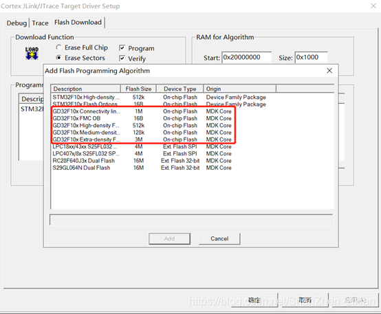
After the installation is complete, you can open the project file, click the Flash \ Configue flash Tools \ Debug \ Settings \ Flash Download \ Add, if you see these Flash GD in the figure below ok.
2, modified firmware library 32 clock
library V3.x, the start time of macros are defined in the header file xxx32f10x.h; V3.0 in previous libraries, which start time is in macro definitions in xxx32f10x_rcc.c (HSEStartUp_TimeOut). Search to find.
Before the amendment: // # the DEFINE HSE_STARTUP_TIMEOUT ((uint16_t) 0x0500) / * <for HSE Start up Time OUT! /
Modified: #define HSE_STARTUP_TIMEOUT ((uint16_t) 0xFFFF) / ! <Time for HSE OUT * Start up /
Reason for the modification is some difference GD and STM32 crystal portion of the circuit design, the two parameters are not the same requirements of the external high speed oscillator, modifications HSE_STARTUP_TIMEOUT macro definition can guarantee the normal crystal vibrating. In fact, of course, some applications can not modify the usual run, this is due to differences in the parameters of the crystal caused, but in order to ensure the normal operation of the program or modify this macro definition is better.
3, the delay time to modify the software.
GD clock speed is 108M, ST is larger than 72M, run faster code. So if used while a function or a function for delay, delay time must be shorter, which is useful if you program the delay as a function of IIC or SPI clock line communication delay, you may need to modify the delay time a. Official gives such a data: Measured following this piece of code: ST execute the function of delay time is 7.4us, GD perform the function of delay time is 5.4us.
void delay(void)
{
    u8 i;
	for(i=0;i<75;i++);
}
This is just as a reference, with the longer delay time, this gap will be different, can not be calculated by linear. Oscilloscope, then the best measured with an oscilloscope.
Then the government has also given some IIC code, you can look at.
IO simulation I2C write his check response function is as follows:
#define SDA_Status() GPIO_ReadInputDataBit(GPIOA, GPIO_Pin_1)
void CheckACK(void)
{
    cAcknowledge=TRUE
    if(SDA_Status())
    {
        cAcknowledge=FalSE;
    }
}
This code is executed ST above OK, but not functioning properly at the top GD, GD fact, this is due to the implementation of faster, ACK signals also come out, the statement has been executed completed. Proposed modification of code:
#define SDA_Status() GPIO_ReadInputDataBit(GPIOA, GPIO_Pin_1)
void CheckACK(void)
{
    u8 ErrTimer=0;
    cAcknowledge=TRUE
    while(SDA_Status())
    {
        ucErrTime++;
 		if(ucErrTime>250)
 		{
 			cAcknowledge=FalSE;
 		}
    }
}
If your program uses only the most commonly used functions, such as external interrupts, timers, serial port that, then in accordance with point 3 above after the completion of change you can burn to a GD with the above program the STM32, Flash to choose the same capacity GD chip models, operating procedures should be no problem. And if you use some special, such as data stored in internal Flash microcontroller, IIC use MCU internal standard, SPI interfaces (we often use ordinary analog IO port, do not use SCM library). So in some places you will need to be modified, and I have some bug GD interior design given an official cause, but because the information is older, I do not have eleven to test, so I will not list out. I just tested my problems still exist for everyone to talk about.
Third, some of the problems with the GD library functions occur ST
1, Flash
Flash GD fast execution speed, but slower write operation, it is necessary to modify the following several functions when the Flash operation:
FLASH_Status FLASH_EraseOptionBytes(void);
FLASH_Status FLASH_ProgramOptionByteData(uint32_t Address, uint8_t Data);
FLASH_Status FLASH_EnableWriteProtection(uint32_t FLASH_Pages);
FLASH_Status FLASH_ReadOutProtection(FunctionalState NewState);
The four above has the following function inside a code which:
key( FLASH->OPTKEYR = FLASH_KEY1;FLASH->OPTKEYR = FLASH_KEY2;)
We need to add the code after this one two __nop () statement or an increase While ((FLASH-> CR & 0x200)!); // Wait OPTWRE statement to increase the waiting time. For example, change the following codes:
/* Authorize the small information block programming */
FLASH->OPTKEYR = FLASH_KEY1;
FLASH->OPTKEYR = FLASH_KEY2;
While( ! (FLASH->CR & 0x200 ) );// Wait OPTWRE
But also to modify the time-out and struck a macro definition reads:
#define EraseTimeout ((uint32_t)0x000B0000)
#define ProgramTimeout((uint32_t)0x00002000)
change into:
#define EraseTimeout ((uint32_t)0x000FFFFF)
#define ProgramTimeout((uint32_t)0x0000FFFF)
2, The USART
the GD MCU and ST compared to when a plurality of transmissions of continuous IDLE bit, as shown below. This application is for no effect, but will affect the delivery time continuous transmission of data. Program need not be modified.
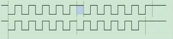
The STM32 USART is when you can send the stop bit is optional 0.5bit, 1bit, 1.5bit and 2bit. When the transmission GD32 USART transmits only 1 bit stop bit or 2bit, if formulated as 0.5bit codes which are transmitted or 1bit 1bit, if formulated as 1.5bit or 2bit 2bit stop bit is sent.
3, EXTI corresponding interrupt abnormal
after EXTI configured If you turn off EXTI, IO hopping along, open EXTI again, the system will respond to external trigger EXTI closing process, in order to circumvent this problem, clear each time you open it again before the break interrupt flag. (There is the problem of small-capacity, high-capacity no)
Well, transplanted to STM32 related content on the GD32 will stop here. If you want to learn more about the difference between ST and GD, you can see my hair before Bowen, if you want to GD support package or official firmware library, you can download at the bottom of the article, if you have any questions or articles in error, please be sure to contact me, thank you! ! !
Differences GD32 and the STM32: https://blog.csdn.net/ShenZhen_zixian/article/details/103250238
GD32 support packages and firmware libraries: https://download.csdn.net/download/ShenZhen_zixian/12004032
