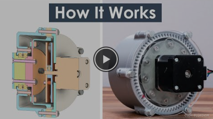
What is a Strain Wave Gear aka Harmonic Drive? The perfect gear set for robotic applications! ?
In this tutorial, we will learn what is a strain wave gear, also known as a harmonic drive. First we'll explain how it works, then design our own model and 3D print it so we can see it in real life and get a better idea of how it works.
You can watch the video below or read the written tutorial below.
1. What is a strain wave gear?
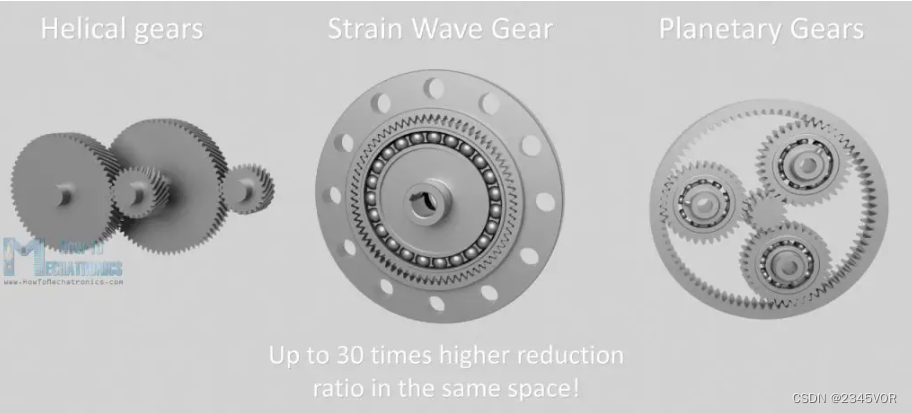
Strain wave gears are a unique mechanical gear system that achieve very high reduction ratios in a compact and lightweight package. Compared with traditional gear systems such as helical gears or planetary gears, it can achieve a higher reduction ratio of up to 30 times in the same space. In addition, it has zero backlash characteristics, high torque, precision and reliability. Therefore, this gear system is used in many applications including robotics, aerospace, medical machines, milling machines, manufacturing equipment, etc.
Strain wave gear was invented by C. Walton Musser in 1957, another name commonly used for it "Harmonic Drive" is actually the brand name of strain wave gear registered by Harmonic Drive Company.
2. Working principle
Ok, let's see how it works now. A harmonic driver has three key components: a wave generator, a flexible spline, and a circular spline.
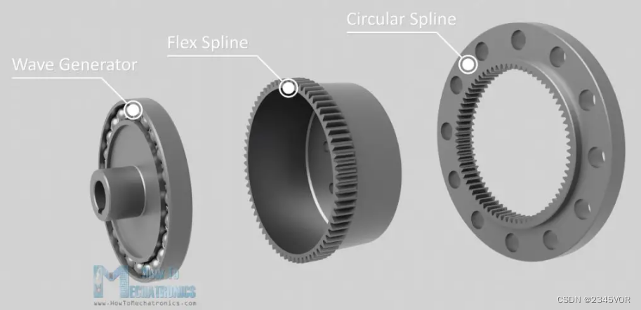
The wave generator has an elliptical shape and consists of an elliptical hub and special thin-walled bearings that follow the elliptical shape of the hub. This is the input to the gear set, which connects to the motor shaft.
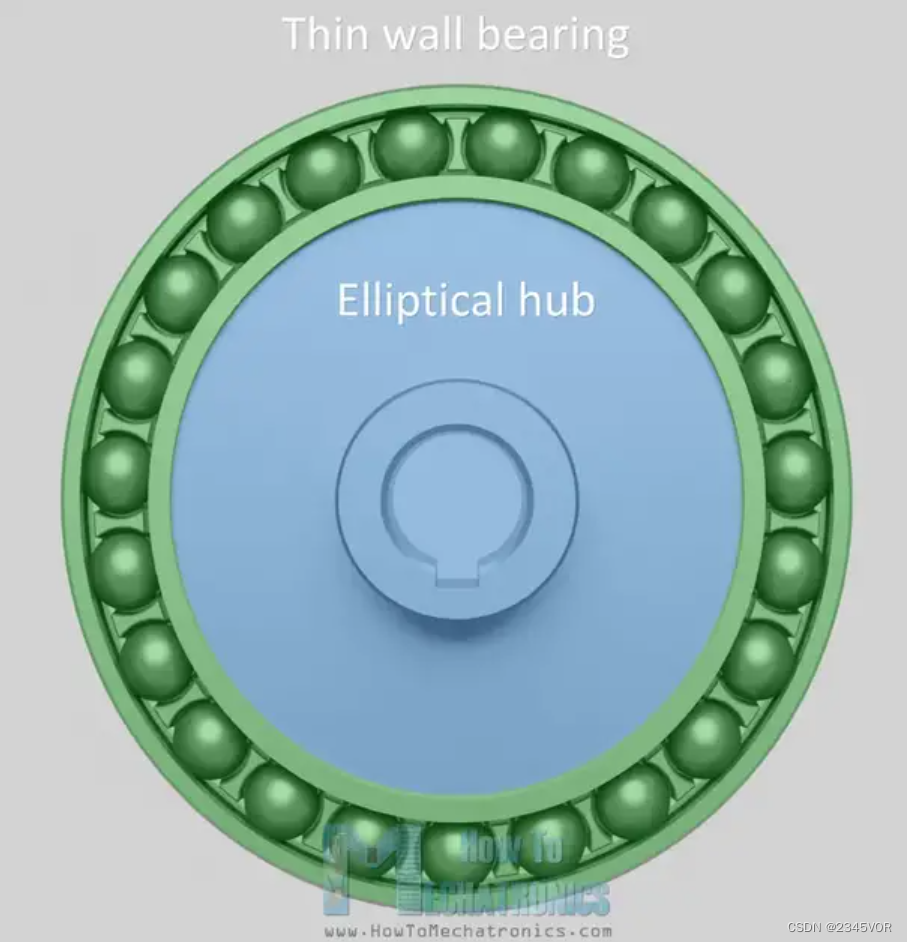
As the wave generator rotates, it creates wave motion.
Flex splines have the form of cylindrical cups and are made of a flexible but torsionally rigid alloy steel material. The sides of the cup are thin, but the bottom is thick and hard.
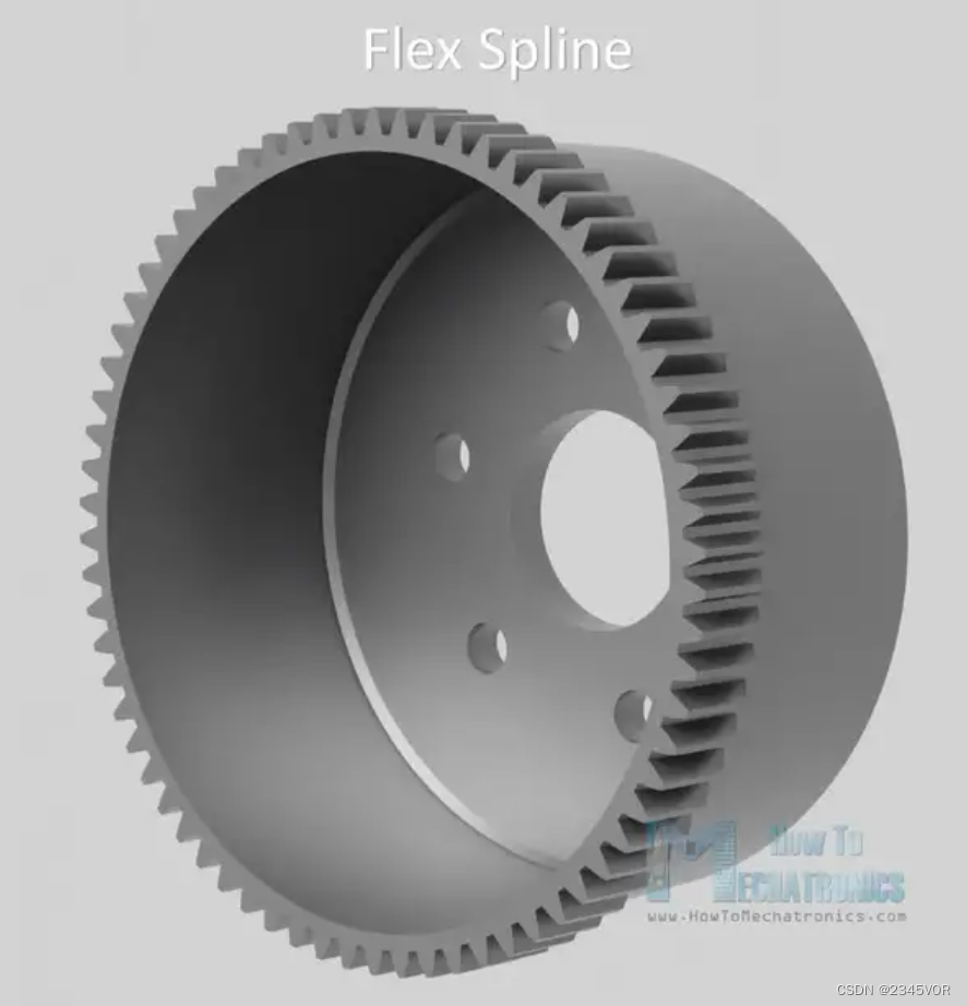
This makes the open end of the cup flexible but the closed end very rigid so we can use it as an output and attach the output flange to it. The flexspline has external teeth on the open end of the cup.
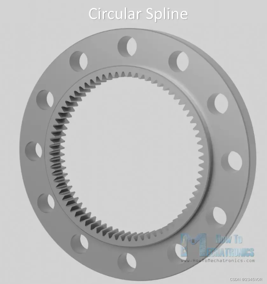
A circular spline, on the other hand, is a rigid ring with teeth inside. The circular spline has two more teeth than the flexspline, which is actually the key design of the strain wave gear system.
So when we plug a wave generator into a flex spline, the flex spline has the same shape as the wave generator.
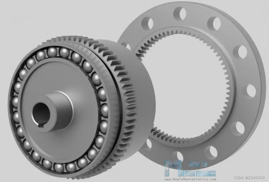
As the wave generator rotates, it radially deforms the open end of the flexible spline. The wave generator and flexible spline are then placed inside the circular spline, meshing the teeth together.
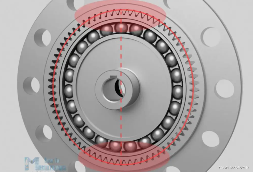
Due to the elliptical shape of the flexible spline, the teeth mesh only in two regions on opposite sides of the flexible spline and span the major axis of the wave generator ellipse.
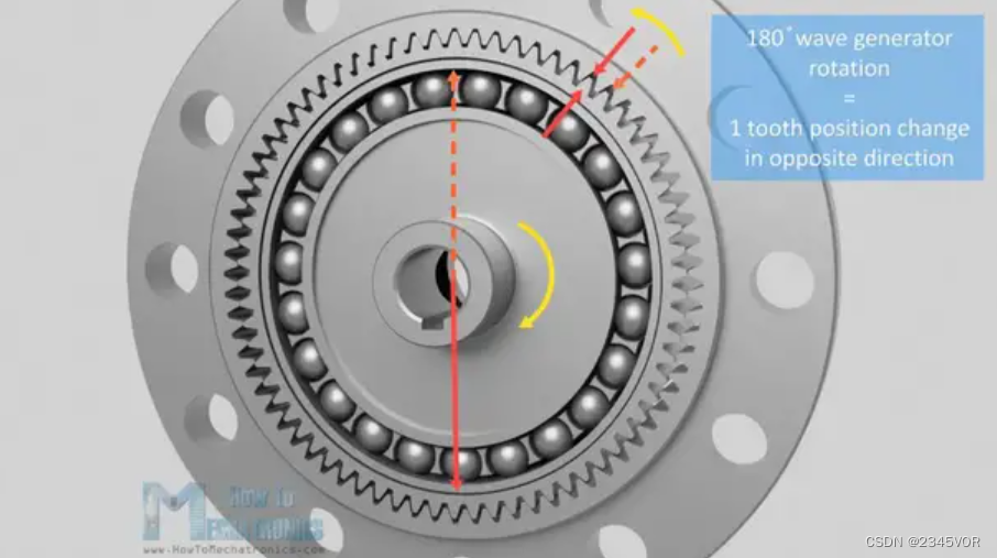
Now, as the wave generator rotates, the flex spline teeth meshing with the circular spline's flex spline teeth will slowly change position. Due to the difference in the number of teeth between the flexible spline and the circular spline, for every 180 degrees of rotation of the wave generator, the tooth engagement will cause the flexible spline to rotate backward relative to the wave generator by a small amount. In other words, the meshing of the flexible spline teeth with the circular spline will advance only one tooth for every 180 degrees of rotation of the wave generator.
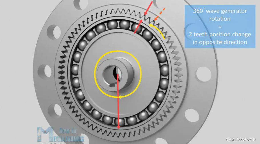
Thus, for a full 360-degree rotation of the wave generator, the flexible spline will change position or advance two teeth.
For example, if the flex spline has 200 teeth, the wave generator must rotate 100 times to advance the flex spline 200 teeth, or is this just a single rotation of the flex spline. This is a 100:1 ratio. In this case, the circular spline will have 202 teeth, since circular splines always have <> more teeth than deflected splines.
We can easily calculate the reduction ratio using the following formula. This ratio is equal to flex spline tooth – circular spline tooth, divided by flex spline tooth.
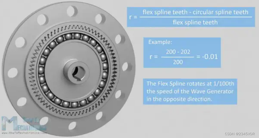
Therefore, taking 200 teeth on the flexible spline and 202 teeth on the circular spline as an example, the reduction ratio is -0.01. This is 1/100th the speed of the wave generator, a negative sigh means the output goes in the opposite direction.
We can get different reduction ratios by changing the number or teeth.
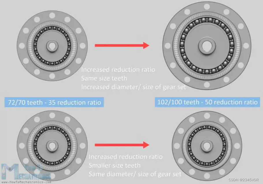
We can do this by changing the diameter of the mechanism while having the same size teeth, or by changing the tooth size to maintain the size and weight of the gear set.
3. Strain Wave Gear – Harmonic Drive 3D Model
Ok, now that we know the theory behind the strain wave gear, let me tell you how I designed it so we can build it with a 3D printer.
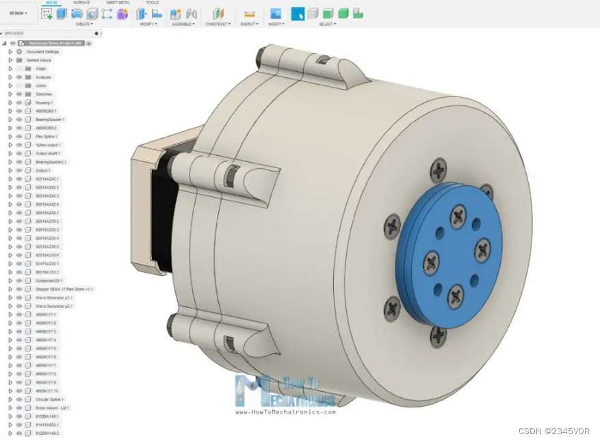
I designed this strain wave gear model using Fusion 360. All of these parts can be 3D printed, so we just need some bolts and nuts and some bearings to complete the assembly. As for the input, I chose to use a NEMA 17 stepper motor.
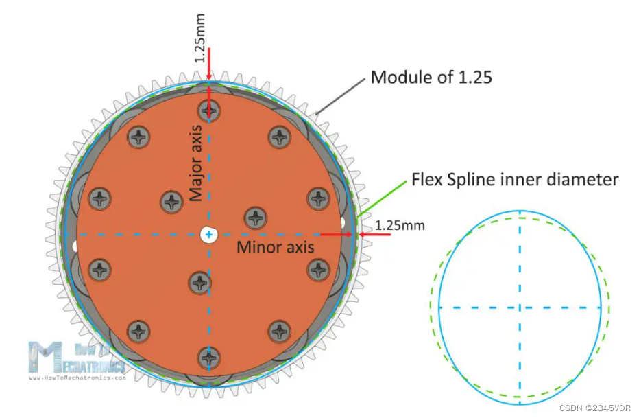
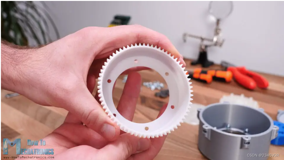
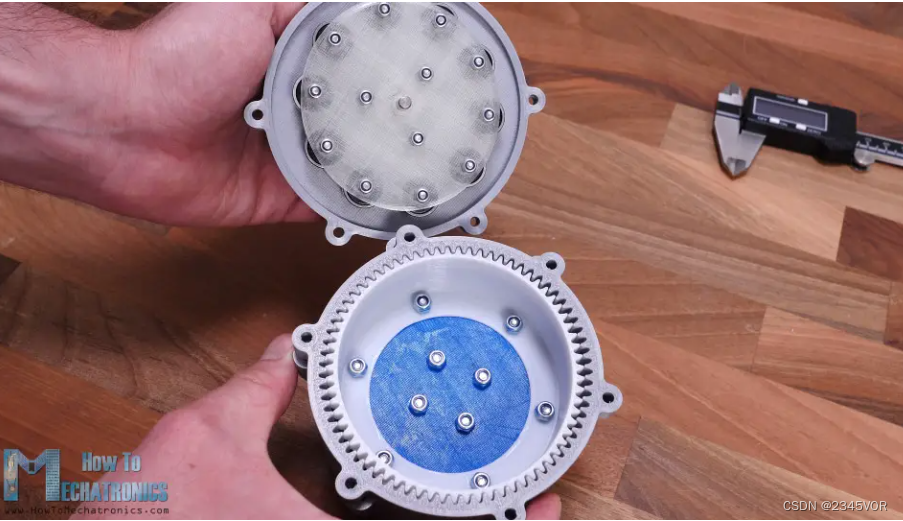
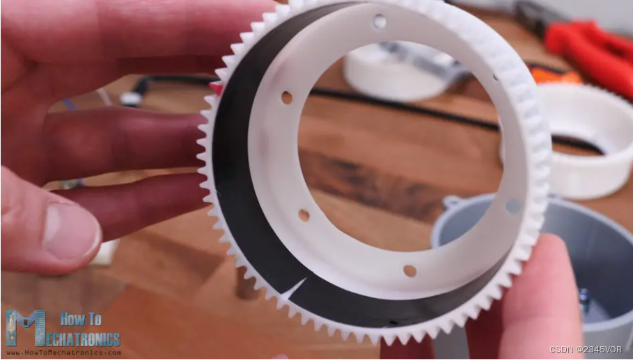
Here's how I designed the 3 key elements of a strain wave gear, the circular spline, the flexible spline, and the wave generator. Since 3D printers have their own limitations in how well they can print, accuracy and precision, I had to first decide on the size of the modules or teeth of the gear. I chose the 1.25 and 72 tooth modules for the circular splines.
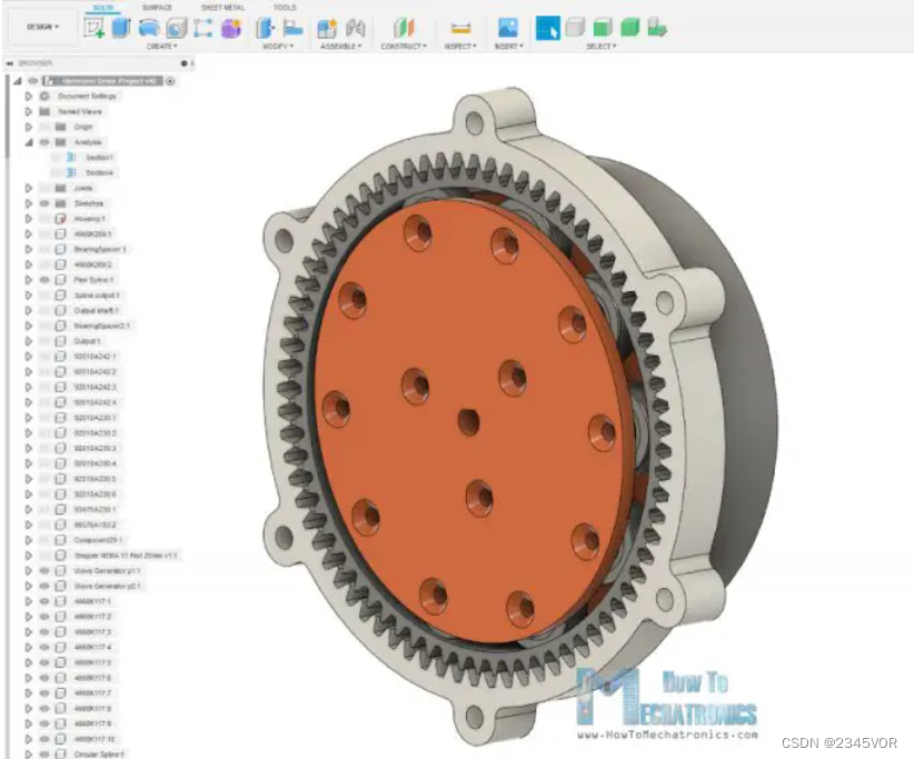
Of course, flexible splines require 2 fewer teeth, or 70 teeth. This results in a 35:1 ratio with a relatively small gear set size.
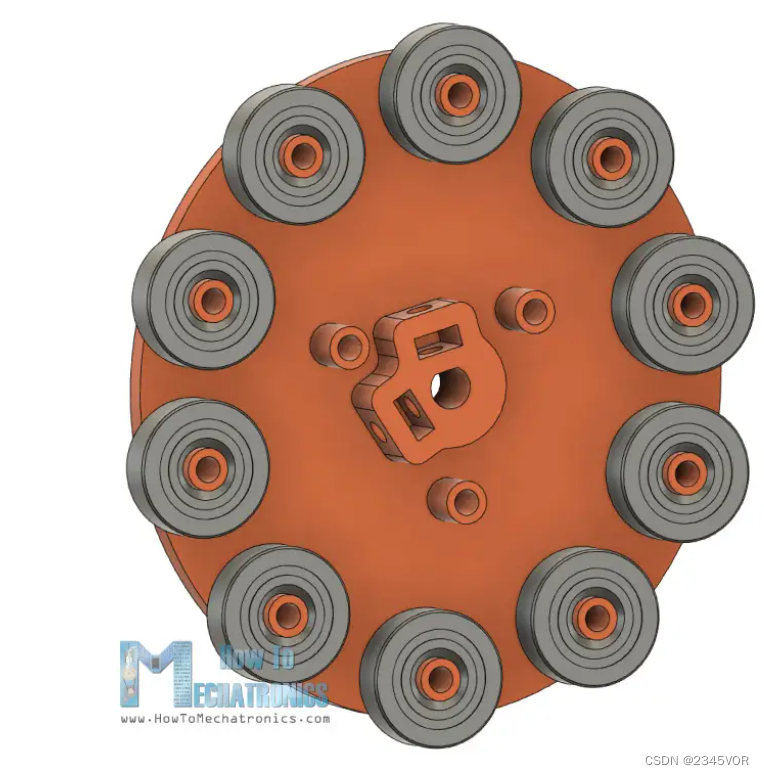
As for the wave generator, we can't really use those special types of thin-walled bearings mentioned earlier because they aren't easy to find. Instead, we'll use plain ball bearings arranged around the circumference of the ellipse. The size of the ellipse shall be based on the size of the inner wall of the flexible spline.
I made the radius of the major axis of the ellipse 1.25mm larger than the radius of the inner wall of the flexible spline. On the other hand, the minor axis radius of the ellipse is 1.25mm smaller.
The wave generator will consist of two parts where the 10 bearings can be easily mounted. One section also has a shaft coupler suitable for holding NEMA 17 stepper motors.
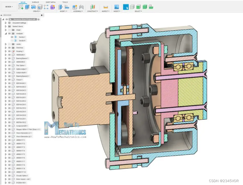
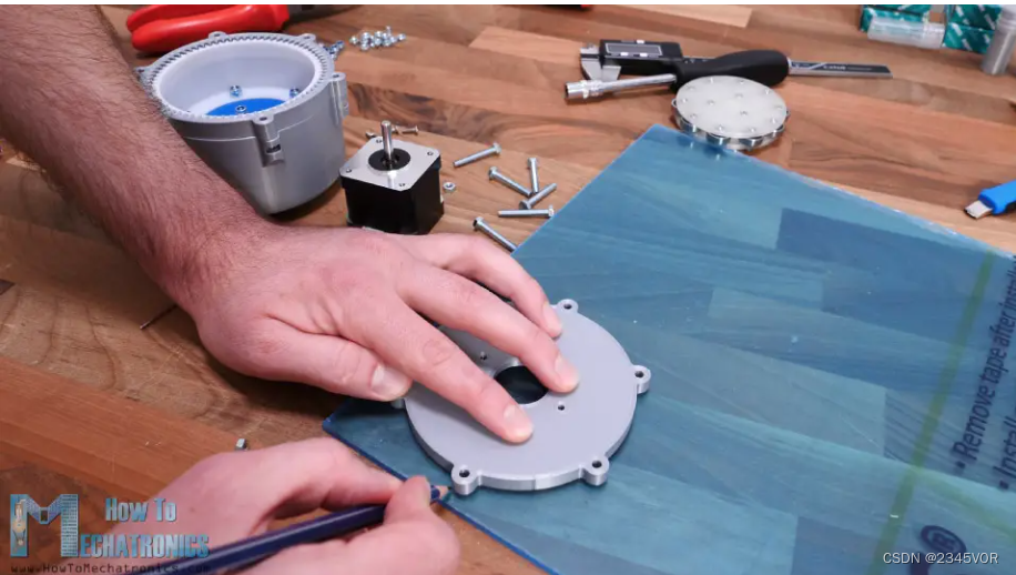
The rest is designed around these 3 key components. On the output side of the housing we will insert two bearings with an outer diameter of 47 mm and we will secure them with the help of some bolts and nuts.
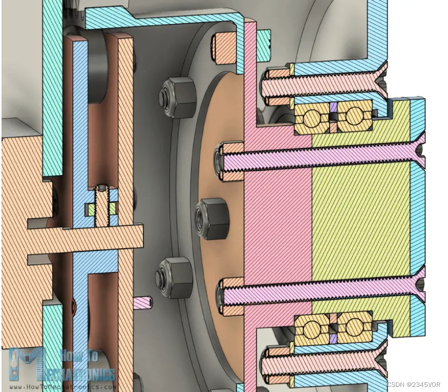
The output flange is made of two parts connected with bolts and nuts, so we can easily fix it on the two bearings.
Below are the STL files required for 3D printing.
You can download this 3D model or explore it in Thangs' browser.
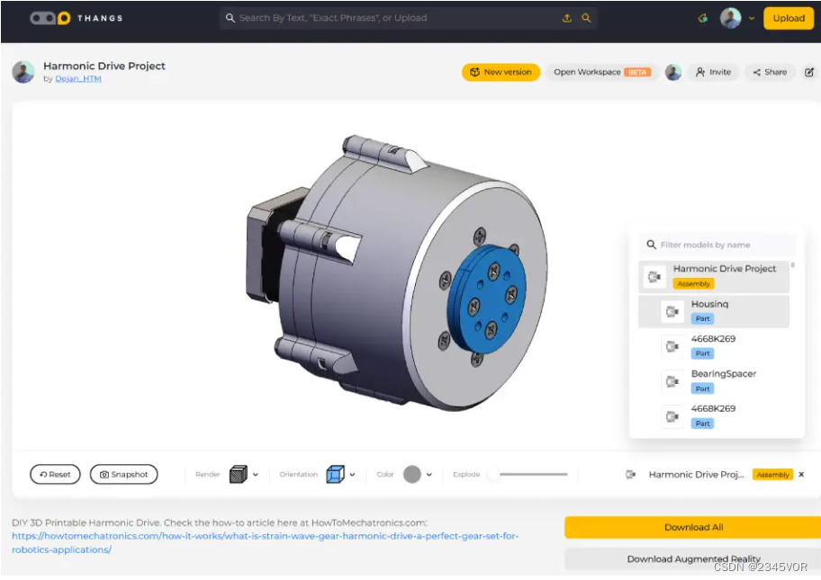
Download 3D models in Downs .
STL files required for 3D printing:
Icon Strain Wave Gear - Harmonic Drive STL
File
1 File 1.44 MB SEE ALSO: Best 3D Printers for Beginners and Makers [Updated 2021]
4. 3D Printed Strain Wave Gears – Harmonic Drive
Ok, now it's time to 3D print the parts. When 3D printing gears, it is very important to use the horizontal scaling feature in your slicing software.
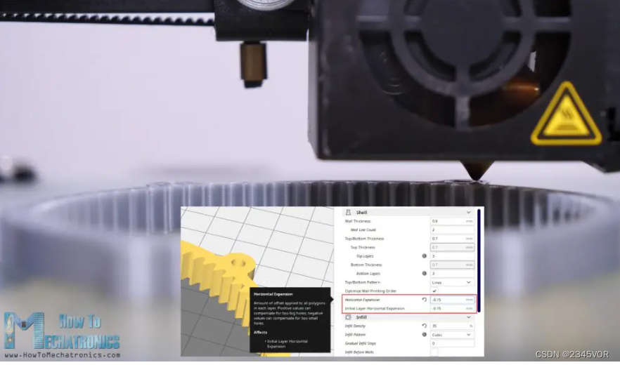
I set mine to -0.15mm and got relatively good accuracy on my prints. Note that this may vary by printer. If we don't use this feature, the print will be slightly larger due to the expansion of the filament when printing, and the parts or gears will not mesh properly.
I printed all the parts using my Creality CR-10 3D printer, which I think does a pretty good job considering its price point.
So, here are all the 3D printed parts.
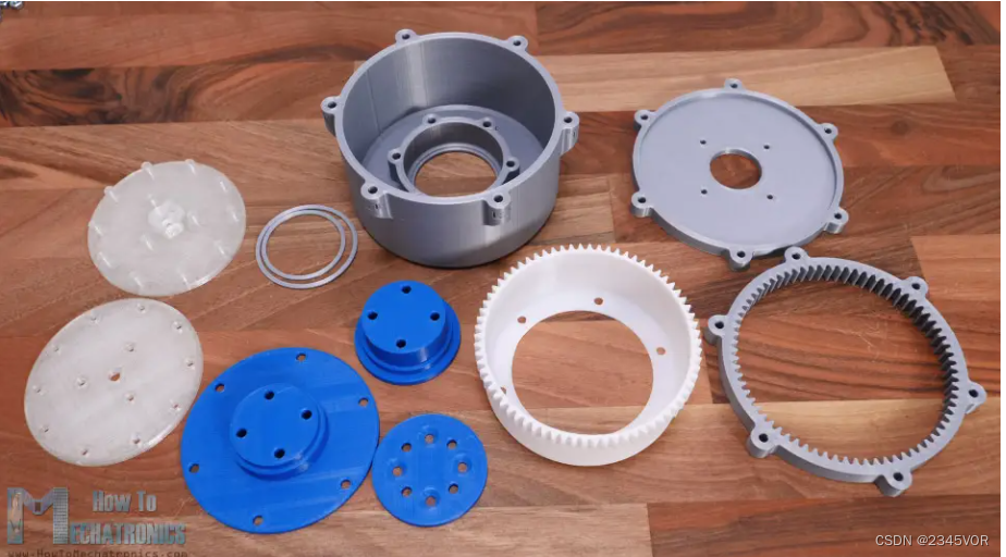
We just need some bolts, nuts and some bearings to complete the assembly of the harmonic drive.
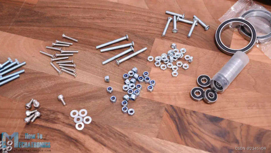
Here is a complete list of all components:
螺栓:
M3x16 – 13 件
M3x12 – 4
M4x12 – 6
M4x25 – 6
M4x30 – 6
M4x40 – 4
螺母:
M3 自锁 – 13
M4 自锁 – 16
M4 – 10
轴承:
(外径) 16 毫米 x (英寸) 5 毫米 x (宽) 5 毫米 – 10
(外径) 47 毫米 x (英寸) 35 毫米 x (宽) 7 毫米 – 2
电子学:
步进电机 – NEMA 17
A4988 步进驱动器
Arduino
直流电源
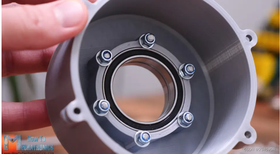
I started the assembly by inserting the two output bearings into the housings. The outer diameter of the bearing is 47mm and the inner diameter is 35mm. Like I said, I used -0.15mm horizontal expansion compensation when slicing the parts, so the bearings fit very tight in the housings.
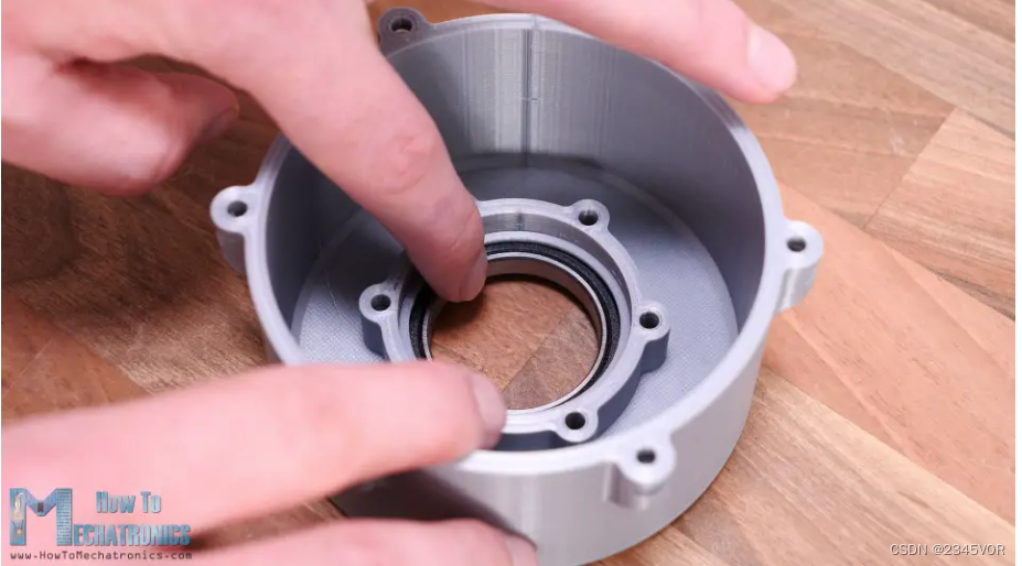
Between the two bearings I placed 1.5mm 3D printed distance rings. To secure the bearing to the housing we need six M25 countersunk bolts of length 4mm. We'll also be using M4 washers which will just touch the outer race of the bearing so they will hold the bearing in place in the housing.
Next is the flexible spline. The walls of the mug are only graduated at 1.2mm, so although it's printed in PLA, it's still flexible at the open end.
At the closed end of the flexspline we can attach the output flange with six M4 bolts. Once fixed, the flexible spline is now a little more flexible than before, but the closed end is now very rigid.
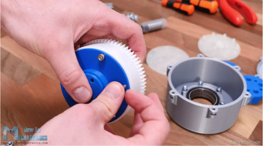
Next, we need to insert the flexspline into the bearing. The output flange goes halfway through the first bearing. On the other side we will insert another part of the output flange which will fit right between the two bearings.
I proceeded to place four M4 nuts in the slots on the output shaft. These nuts will be used to attach or connect things to the output of the gear set.
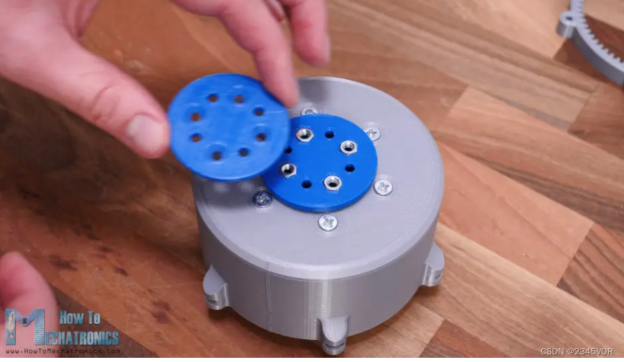
To complete the output shaft, on top of this I placed another part that will cover the nut, and using 4 M40 bolts of length 4mm, I could finally hold the two output parts together. Now the flexspline and output shaft can be fixed freely on the housing.
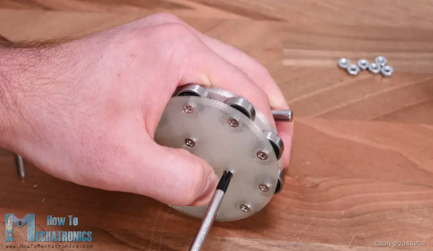
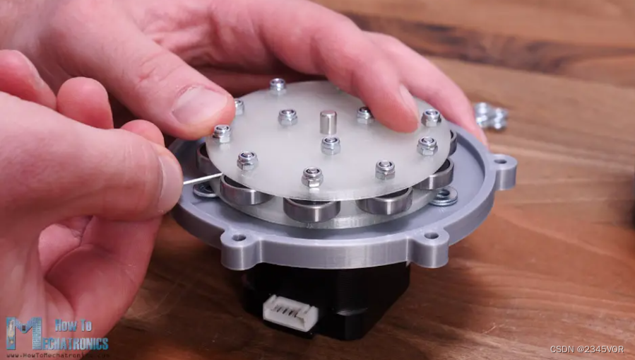
Ok so next we have the circular splines which will hold the gear unit cover and motor mount to the housing. But before we can do that, we need to assemble the wave generator. Here first we need to insert two M3 nuts. These nuts will be used to secure the wave generator to the motor shaft using two countersunk screws.
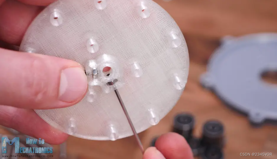
Next we can start inserting the 10 bearings into place. We can notice here that the distance of the bearing from the wall is only a little bit away from the small edge at the bottom of the shaft. The other part of the wave generator also has this edge so the bearings don't touch the wall. We're going to hold the bearing, actually the whole wave generator, with 16mm long M3 bolts and some nuts.
Next we need to attach the wave generator to the motor, but before that we need to attach the motor to the motor bracket and the cover of the gear set. The wave generator should be 2mm from the motor cover, so I used two washers as guides when inserting the wave generator in place. Then we just need to tighten the countersunk screws, which are positioned to reach between the bearings.
Finally, we can plug the wave generator into the flexible spline and tie everything together. We should first adjust the flexible spline to be elliptical meshed with the circular spline, and then insert the wave generator in the same direction.
To be honest, it might be a bit difficult to do this because we don't have control over the flexsplines due to the motor mount. I could have designed it a bit differently, but I still think it's good enough for demonstration purposes.
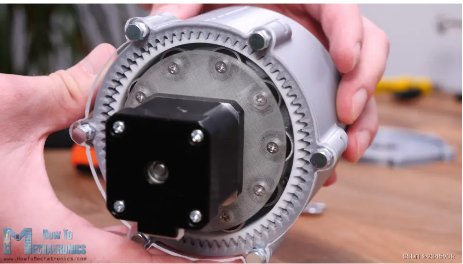
Now all that is left is to insert the M4 nuts in these housing sockets and secure the circular splines and wave generator to the housing.
That's it, our strain wave gear or harmonic drive is now complete. But when I was done, I thought it would be a bit boring to finish the gear set like this, because we can't see anything but the slowly rotating output shaft. There I decided to replace the 3D printed gear unit cover with acrylic so we could also see what was going on inside.
I had a 4mm tick-tock acrylic sheet so I marked the shape of the lid on it and roughly cut the shape with a hand saw.
Then using a file, I fine-tuned the shape of the acrylic. I used a 3mm drill for the holes and a 25mm Forstner bit for the large hole for the motor. The final shape is pretty good.
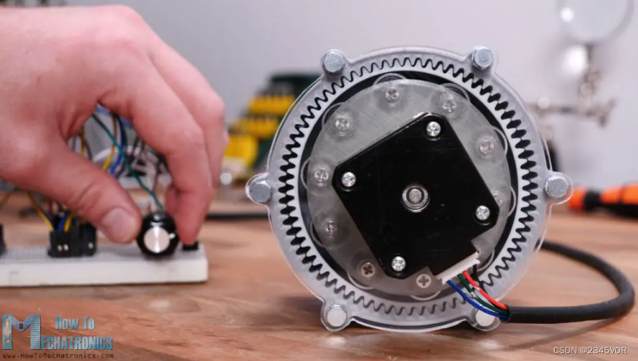
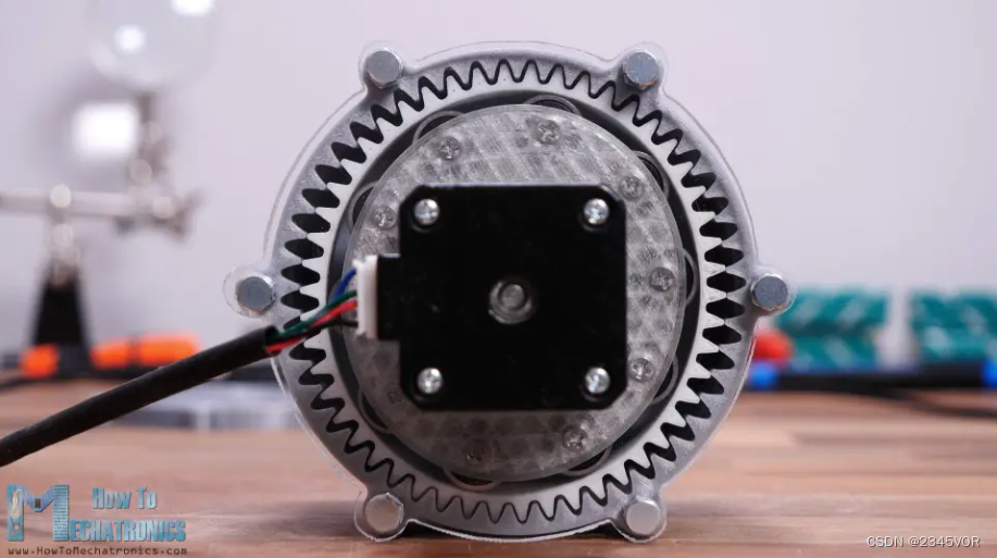
As mentioned, I reassembled the motor and wave generator. We can notice here that I added some nuts between the acrylic and the case to get the proper distance like the cover before.
Now this gear set looks even cooler.
I connected the stepper motor to the Arduino so that I can control the motor speed and direction to better check and see how the system works.
So here it comes. Now we can see how harmonic drives work in real life. In this case, the output shaft is 35 times slower than the input shaft.
Here I've marked one of the flex spline's teeth in red so we can better track it and understand the flex spline's motion. Honestly, it's interesting to see how this thing works.
However, we noticed that flexible splines sometimes jittered or the movement was not as smooth. There are several reasons for this. In this configuration, the problem was that I hand made the acrylic motor mount, so the motor didn't fit perfectly in the center. When using the original 3D printed motor bracket, the movement is smoother.
We can also notice that our harmonic drivers are far from zero clearance. As I said before, this is because of the limitations of these types of 3D printers and how well they can print. It's not just about how well the tooth outlines are printed, but also about the accuracy of the overall dimensions. For example, here I used insulating tape on the inside of the flax splines, with only a 0.18mm scale, with which I got better results.
5. Summary
So, I guess, it's all about testing and tweaking the print for better results. I also tried printing gears with the 1.75 module, but didn't get good results.
Actually, when using the original 3D printed lid, the movement is smoother, but still not good enough.
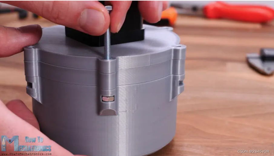
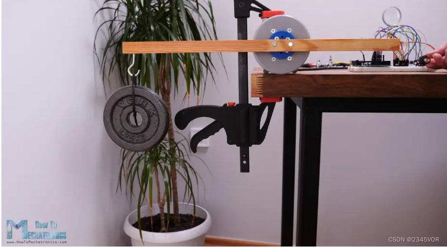
I also try lifting some weights. At a distance of 25 cm, it is able to lift 1.25 kg. The torque is about 3Nm, which is at least 17 times the rated torque of a NEMA 10 stepper motor.
So that's pretty much what this video is all about. I just want to add that this transmission system can easily be designed as a hollow shaft, which is very convenient for robotic applications. So I'll probably use harmonic drives in some of my future videos when I'm making some robotics projects.
I hope you enjoyed this video and learned something new. Don't forget to subscribe, for more tutorials and projects,
Translation address: https://howtomechatronics.com/how-it-works/what-is-strain-wave-gear-harmonic-drive-a-perfect-gear-set-for-robotics-applications/
Video address: https: https://youtu.be/xlnNj9F37MA