Packet Tracer - Who will hear the radio?
Target
Part 1: Observing Broadcast Traffic in a VLAN Implementation
Part 2: Completing the Reflection Questions
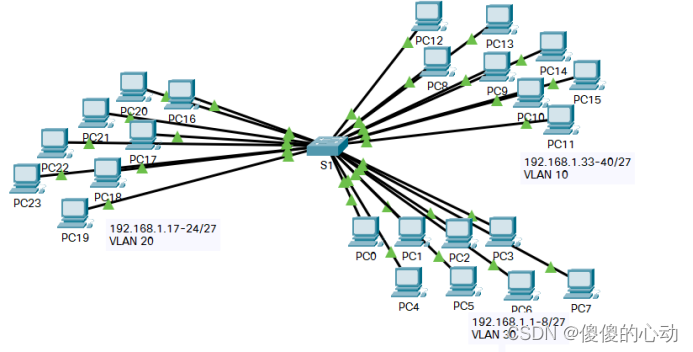
Topology
Scenes
In this exercise, a Catalyst 2960 switch with 24 ports will be fully populated. All ports are used. You will observe broadcast traffic in a VLAN implementation and answer some reflection questions.
Part 1: Observing Broadcast Traffic in a VLAN Implementation
Step 1: Generate traffic using ping.
a. Click PC0 , then click the Desktop tab > Command Prompt .
b. Enter the ping 192.168.1.8 command. The ping command should succeed.
Unlike LANs, VLANs are broadcast domains created by switches. Use the Packet Tracer simulation mode to ping the terminal device in its own VLAN. Based on your observations, answer the questions in Step 2.
Step 2: Generate and inspect broadcast traffic.
a. Switch to simulation mode.
b. Click Edit Filter in the Simulation panel . Uncheck the Show all/None checkbox. Check the ICMP checkbox.
c. Click the Add Complex PDU tool, which is the open envelope icon on the right toolbar.
d. Hover the mouse cursor over the topology map and the pointer changes to an envelope with a plus sign (+).
e. Click on PC0 to use as the source for this test message and the Create Complex PDU dialog window will open. Enter the following values:
· Target IP address: 255.255.255.255 (broadcast address)
· Serial number: 1
· Single sending time: 0
In PDU Setup, the default setting for Select Application: is PING. Please list at least 3 other apps.
DNS, FINGER, FTP, HTTP, HTTPS, IMAP, NETBIOS, PING, POPP3, sftp, smtp, snmp, ssh, TELNET, TFTP and others
f. Click Create PDU . At this point, this test broadcast packet is displayed in the event list of the simulation panel. Also appears in the PDU list window. This is the first PDU for Scenario 0.
g. Click Capture/Forward twice. What happened to the packet?
The packet is sent to the switch and then broadcast to all PCs belonging to the same VLAN, in this case VLAN 10
h. Repeat this process for PC8 and PC16 .
Part 2: Completing the Reflection Questions
- If a PC in VLAN 10 sends a broadcast message, which devices will receive the message?
All end devices on VLAN 10
- If a PC in VLAN 20 sends a broadcast message, which devices receive the message?
All end devices on VLAN 20
- If a PC in VLAN 30 sends a broadcast message, which devices will receive the message?
All end devices on VLAN 30
- What happens to frames sent from a PC in VLAN 10 to a PC in VLAN 30?
It will be deleted because they are not on the same VLAN.
- If a PC connected to port 11 sends a unicast message to a PC connected to port 13, which port on the switch will light up?
Ports 11 and 13 will light up
- If a PC connected to port 2 sends a unicast message to a PC connected to port 23, which port on the switch will light up?
packets will be dropped
- What are the collision domains on the switch in terms of ports?
Each port is its own collision domain
- In terms of ports, what are the broadcast domains on the switch?
Each VLAN is its own broadcast domain
Experiment link: https://pan.baidu.com/s/12r5bQUYaIhRp07i9k66pIQ?pwd=6115
Extraction code: 6115
--Sharing from Baidu Netdisk super member V2