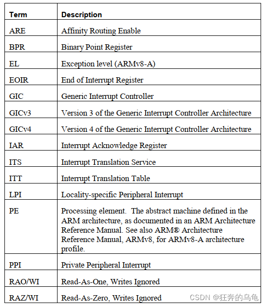
1、Terms and Abbreviations
2、Introduction
本系列博客文档准备转译通用中断控制器体系结构的第3版(GICv3)手册。它主要面向为ARMv8-A编写代码的软件工程师。
GIC 的全称为 General Interrupt Controller,主要作用可以归结为:接受硬件中断信号并进行简单处理,通过一定的设置策略,分给对应的CPU进行处理。
本博文提供了GICv3功能的以软件为中心的概述,并描述了GICv3兼容中断控制器的操作。它也是一本关于如何配置用于裸机环境的GICv3中断控制器。
详细描述请参考 ARM® Generic Interrupt Controller Architecture Specification
GIC architecture version 3.0 and 4.0.
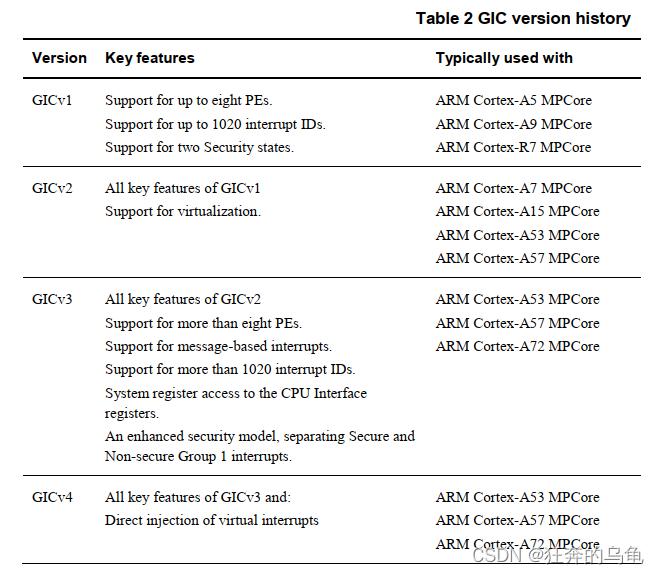
2.2 Brief history of the GIC architecture
3、GICv3 fundamentals
3.1.1 ARM 中断类型
- SGI: Software Generated Interrupt,软件产生中断,中断号是 0-15。通过向SGI寄存器写数触发,可用于CPU间的通信,比如时间同步,全局进程调度信息等。每个 PE 都有这么多 SGI 号。The Redistributor provides the configuration settings for PPIs and SGIs.
- PPI: Private Peripheral Interrupt,私有外设中断,中断号是 16~31。这些中断一般是发送给特定的CPU的,比如每个CPU有自己对应的 Generic Timer,产生的中断信号就发送给这个特定的CPU进行处理。每个 PE 都有这么多 PPI 号。The Redistributor provides the configuration settings for PPIs and SGIs.
- SPI: Shared Peripheral Interrupt,共享外设中断,中断号是 32~1019。比如按键触发一个中断,手机触摸屏触发的中断,共享的意思是说可以从多个 PE 中选择一个发送处理,当然也可以指定发送给某个 PE。The Distributor provides the routing configuration for SPIs, and holds all the associated routing and priority information.
特殊中断号。1020-1023。这个在 GICv3 中用于指示特别的场景,例如给 EL3 的软件使用。
保留中断号,1024-8191。 - LPI: Locality-specific Peripheral Interrupt,局部外设中断,中断号 >=8192 。LPI 没有 active or active and pending state,得到响应后由处理器自动转入 inactive 状态。LPIs are new in GICv3, and they are different to the other types of interruptin a number of ways . In particular, LPIs are always message-based interrupts,and their configuration is held in tables in memory rather than registers. NOTE: LPIs are only supported when GICD_CTLR.ARE_NS==1.
3.1.2 Interrupt Identifiers
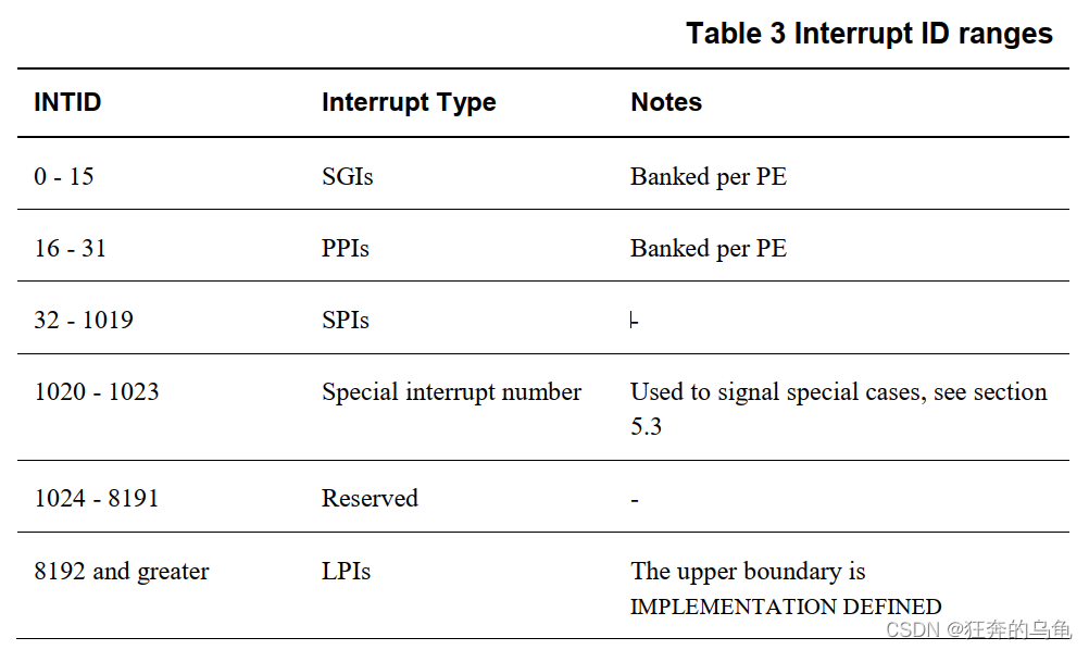
每个中断源由一个ID号标识,称为INTID。可用的
INTID分为多个范围,每个范围分配给一种特定类型的中断。
 ### 3.1.3 How interrupts are signaled to the interrupt controller
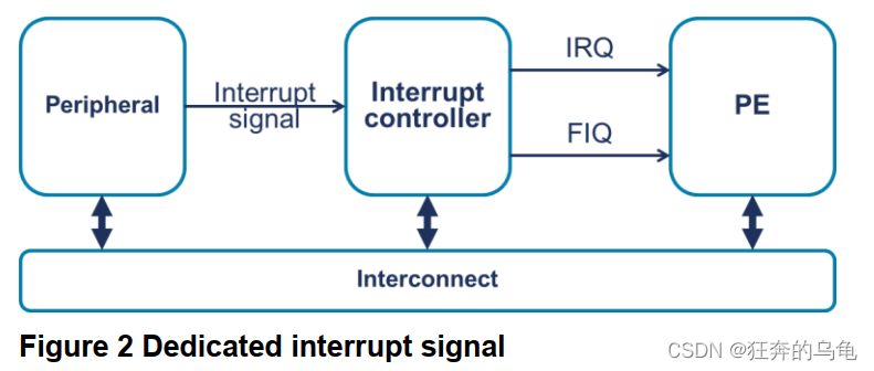
传统上,中断是使用专用接口从外设向中断控制器发送信号硬件信号。
 GICv3支持此模型,另外还支持基于消息的中断。基于消息的中断是通过写入中断控制器中的寄存器来设置和清除的中断。
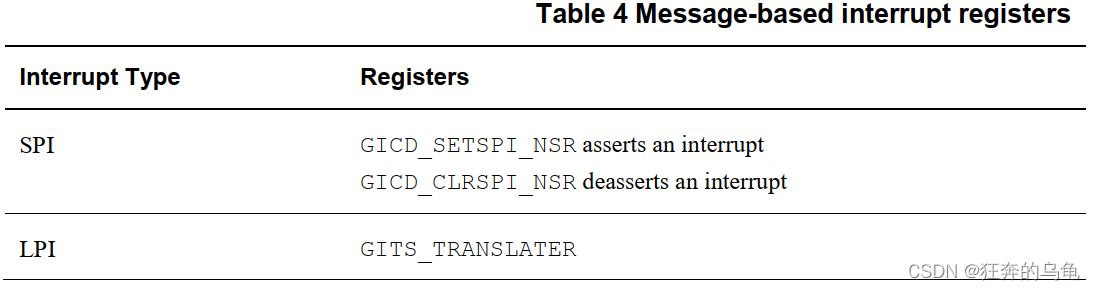
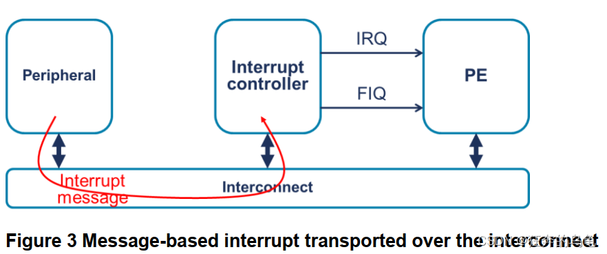 使用一条消息将中断从外设转发到中断控制器将删除每个中断源对专用信号的要求。这对于硬件来说是一个优势大型系统的设计者,其中可能存在数百甚至数千个信号通过SoC布线,并在中断控制器上会聚。在GICv3中,SPI可以是基于消息的中断,但LPI始终是基于消息的中断。不同的寄存器用于不同的中断类型,如表4所示。
 Impact of message-based interrupts on software
无论中断是作为消息发送还是使用专用信号发送,都不会对传输方式产生太大影响中断处理代码处理中断。可能需要一些外围设备的配置。例如,可能有必要指定中断控制器的地址。
3.2 Interrupt state machine
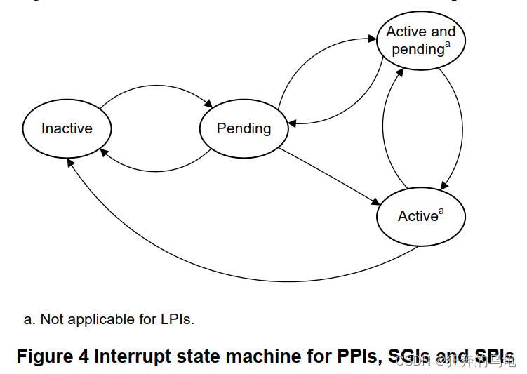
中断控制器为每个SPI、PPI和SGI中断源维护一个状态机。这
状态机由四种状态组成:
-
In’a’ctive 不活跃的
中断源当前未断言。 -
Pending 挂起的
中断源已断言,但中断尚未确认PE首个被响应。 -
Active 忙碌的
中断源已被断言,中断已被PE确认。 -
Active and Pending 活动和挂起的
中断的一个实例已被确认,另一个实例正在挂起。
注意:LPI没有活动或活动和挂起状态。有
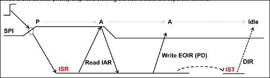
 ### 3.2.1 Level sensitive(电平触发处理)
 Inactive to Pending
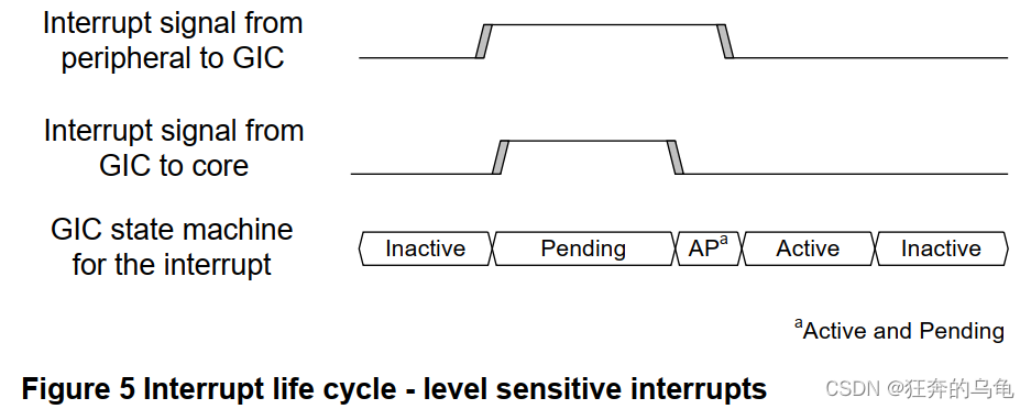
An interrupt transitions from inactive to pending when the interrupt source is asserted.
At this point the GIC asserts the interrupt signal to the PE (if the interrupt is enabled and is of
sufficient priority).
Pending to Active & Pending
The interrupt transitions from pending to active and pending when a PE acknowledges the
interrupt by reading one of the IARs (Interrupt Acknowledge Registers) in the CPU interface. This
read is typically part of an interrupt handling routine that executes after an interrupt exception is
taken. However, software can also poll the IARs.
At this point the GIC deasserts the interrupt signal to the PE.
Active and Pending to Active
The interrupt transitions from active and pending to active when the peripheral de-asserts the
interrupt signal. This typically happens in response to the interrupt handling software that is
executing on the PE writing to a status register in the peripheral.
Active to Inactive
The interrupt goes from active to inactive when the PE writes to one of the EOIRs (End of
Interrupt Registers) in the CPU interface. This indicates that the PE has finished handling the
interrupt.
具体流程如下:
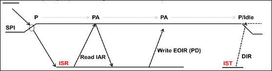
- 外部高电平中断到达,中断状态置为pending状态。
- 软件读取IAR寄存器,表示PE认可该中断。但中断依然为高,中断状态进入pending and active状态。
- 软件中断处理完毕后,写EOIR寄存器,表示优先级重置。过一段时间后,写DIR寄存器,中断状态被置为idle状态。
3.2.2 Edge-triggered(边沿触发处理)
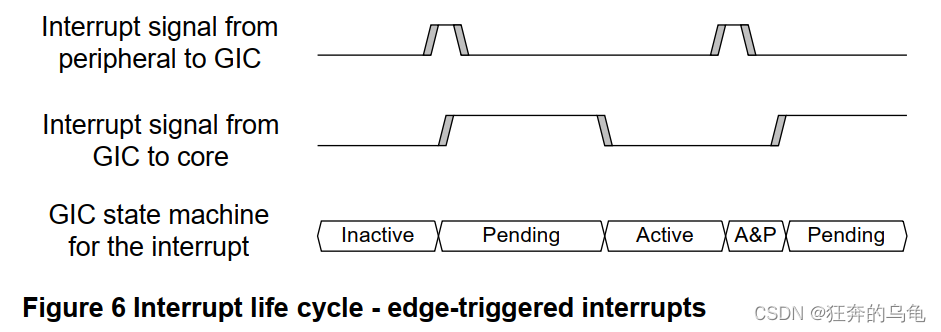 Inactive to Pending
An interrupt transitions from inactive to pending when the interrupt source is asserted.
At this point the GIC asserts the interrupt signal to the PE (if the interrupt is enabled and is of
sufficient priority).
Pending to Active
The interrupt transitions from pending to active when a PE acknowledges the interrupt by reading
one of the IARs in the CPU interface. This read is typically part of an interrupt handling routine
that executes after an interrupt exception is taken. However, software can also poll the IARs.
At this point the GIC de-asserts the interrupt signal to the PE.
Active to Active and Pending
The interrupt goes from active to active and pending if the peripheral re-asserts the interrupt
signal.
Active and Pending to Pending
The interrupt goes from active and pending to pending when the PE writes to one of the EOIRs in
the CPU interface. This indicates that the PE has finished handling the first instance of the
interrupt.
At this point the GIC re-asserts the interrupt signal to the PE.
具体流程如下:
- 外部边沿中断到达,中断状态被置为pending状态。
- 软件读取IAR寄存器值,表示PE认可该中断,中断状态被置为active状态。
- 软件中断处理完毕后,写EOIR寄存器,表示优先级重置。过一段时间后,写DIR寄存器,中断状态被置为idle状态。
3.3 Affinity routing(亲和路由)
GICv3使用关联路由来识别连接的PE,并将中断路由到特定PE或PEs组。PE的关联性表示为四个8位字段:
<affinity level 3>.<affinity level 2>.<affinity level 1>.<affinity level 0>
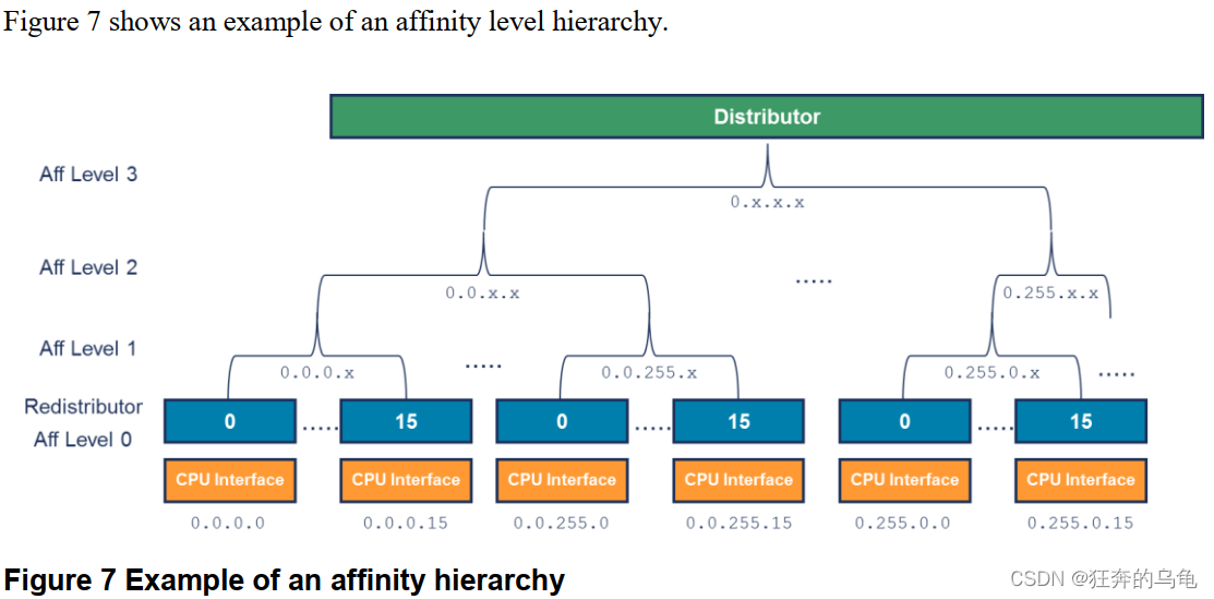
在关联级别0上有一个重新分发器。每个重分发器都连接到一个CPU接口。再分配者控制SGI、PPI和LPI,见第4章。亲和性方案与ARMv8-A中使用的方案相匹配,与中报告的PE的亲和性相匹配MPIDR_EL1。系统设计者必须确保MPIDR_EL1指示的关联值为与连接至PE的再分配器的GICR_TYPE3指示的相同。不同亲和力级别的确切含义由特定处理器和SoC定义。
以下是一些例子:
. ..
...
在一个实现中不太可能存在所有可能的节点。例如,一个移动设备的SoC可以具有类似以下布局:
0.0.0.[0:3] Cores 0 to 3 of a Cortex-A53 processor
0.0.1.[0:1] Cores 0 to 1 of a Cortex-A57 processor
In ARMv8-A, AArch64 state supports four levels of affinity. AArch32 state, and ARMv7, can
only support three levels of affinity. This means a design that uses AArch32 state is limited to a
single node at affinity level 3 (0.x.y.z). GICD_TYPER.A3V indicates whether the interrupt
controller can support multiple level 3 nodes.
NOTE: Although each level 1 node can host up to 256 Redistributors at level 0, in practice it is
likely to be 16 or fewer. This is because of the way the target PEs for an SGI are encoded, as
described in Chapter 7.
在ARMv8-A中,AArch64状态支持四个级别的关联。AArch32状态和ARMv7可以仅支持三个级别的关联。这意味着使用AArch32状态的设计仅限于关联级别为3(0.x.y.z)的单个节点。GICD_TYPER.A3V表示中断是否中断控制器可以支持多个级别3节点。
注意:尽管每个级别1节点在级别0上最多可以承载256个重分发器,但实际上是这样的可能是16个或更少。这是由于SGI的目标PE的编码方式。
3.4 Security model
GICv3体系结构支持ARM信任区技术。必须为每个INTID分配一个组和安全设置。GICv3支持三种组合,如表5所示。
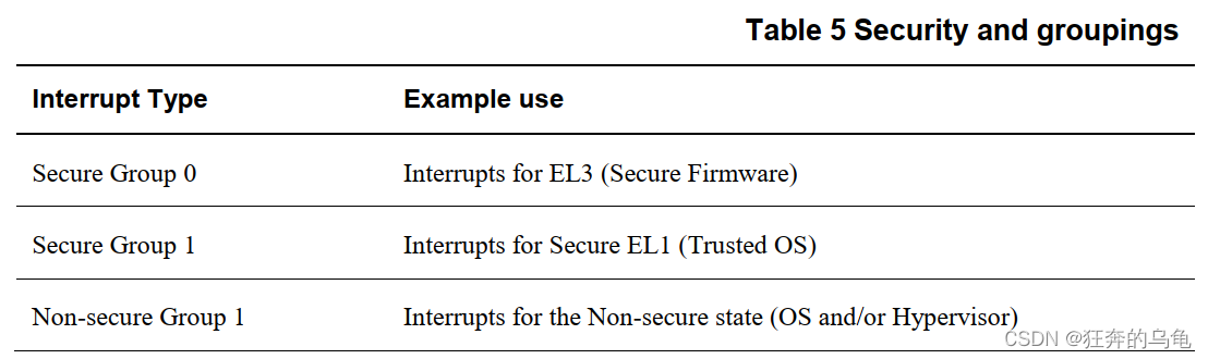
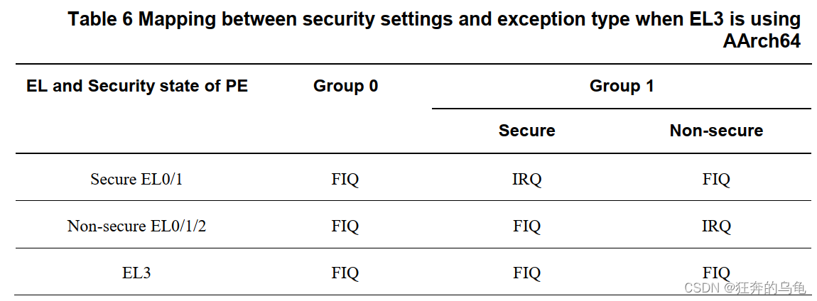
Group 0中断始终以FIQ的形式发出信号。Group 1中断信号为IRQ或FIQ取决于PE的当前安全状态和异常级别。
 这些规则旨在补充ARMv8-A安全状态和异常级别路由控制。图8显示了一个简化的软件堆栈,以及不同类型的在EL0执行时发出中断信号:
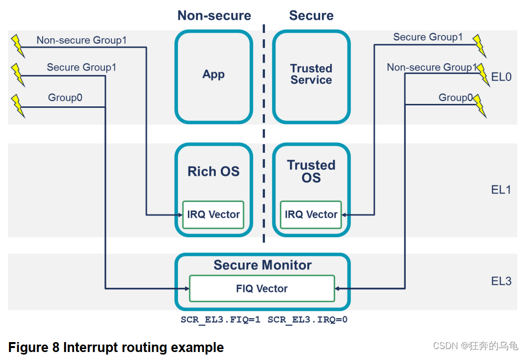 在本例中,IRQ路由到EL1(SCR_EL3.IRQ0),而FIQ路由到EL3(SCR_EL3.FIQ1)。给定表6中描述的规则,在EL1或EL0执行时当前安全状态的第1组中断被视为IRQ。另一个安全状态的中断触发FIQ,异常被带到EL3。这然后允许在EL3执行的软件执行必要的上下文切换。
3.4.1 Impact on software
配置中断时,软件控制INTID到中断组的分配控制器。只有在安全状态下执行的软件才能将INTID分配给中断组。
通常,只有在安全状态下执行的软件才能访问的设置和状态安全中断(Group 0和安全Group 1)。
可以启用从非安全状态到安全中断设置和状态的访问。这是使用GICD_NSACRn和GICR_NSACR寄存器分别控制每个INTID。
注:复位时INTID所属的中断组由实现定义。
注:LPI始终被视为非安全的第1组中断。
3.4.2 Support for single Security state(支持单一安全状态)
Support for two Security states is OPTIONAL in ARMv8-A and GICv3. An implementation can
choose to implement only a single Security state or two Security states.
In a GICv3 implementation that supports two Security states, one Security state can be disabled.
This is controlled by GICD_CTLR.DS.
GICD_CTLR.DS == 0
Two Security states (Secure and Non-secure) are supported
GICD_CTLR.DS == 1
Only a single Security state is supported. On implemenations that only implement a
single Security state, this bit is RAO/WI.
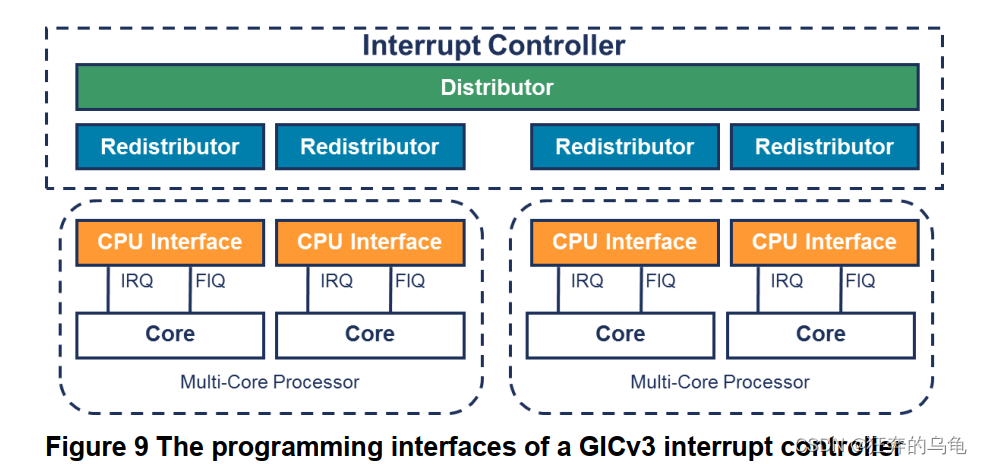
3.5 Programmers’ model
The register interface of a GICv3 interrupt controller is split into three groups:
- Distributor interface.
- Redistributor interface.
- CPU interface.
 Distributor (GICD_*)
The Distributor registers are memory-mapped, and contain global settings that affect all PEs
connected to the interrupt controller. The Distributor provides a programming interface for:
Interrupt prioritization and distribution of SPIs.
- Enabling and disabling SPIs.
- Setting the priority level of each SPI.
- Routing information for each SPI.
- Setting each SPI to be level-sensitive or edge-triggered.
- Generating message-based SPIs.
- Controlling the active and pending state of SPIs.
- Controls to determine the programmers’ model that is used in each Security state (affinity
routing or legacy).
Distributor (GICD_*)
For each connected PE there is a Redistributor. The Redistributors provides a programming
interface for:
- Enabling and disabling SGIs and PPIs.
- Setting the priority level of SGIs and PPIs.
- Setting each PPI to be level-sensitive or edge-triggered.
- Assigning each SGI and PPI to an interrupt group.
- Controlling the state of SGIs and PPIs.
- Base address control for the data structures in memory that support the associated interrupt properties and pending state for LPIs.
Power management support for the connected PE.
CPU interfaces (ICC_*_ELn)
Each Redistributor is connected to a CPU interface. The CPU interface provides a programming
interface for:
- General control and configuration to enable interrupt handling.
- Acknowledging an interrupt.
- Performing a priority drop and deactivation of interrupts.
- Setting an interrupt priority mask for the PE.
- Defining the preemption policy for the PE.
- Determining the highest priority pending interrupt for the PE.
在GICv3中,CPU接口寄存器作为系统寄存器(ICC)访问。在使用这些寄存器之前,软件必须启用系统寄存器接口。这是可控的通过ICC_SRE_ELn寄存器中的SRE位,其中“n”指定异常级别(EL1)-EL3)。
注:在GICv1和GICv2中,CPU接口寄存器为内存映射(GICC_*)。
注:软件可以通过读取ID_AA64PFR0_EL1来检查GIC系统寄存器支持
PE,请参阅ARM®体系结构参考手册,ARMv8,了解有关的ARMv8-A体系结构配置文件
细节。