Article Directory
1. The composition of the smallest system
1. Power supply circuit
It can play a variety of functions such as boosting and lowering voltage, filtering, current stabilization, current limiting, voltage limiting, and short- circuit prevention to ensure clean and stable current and voltage during power supply.
2. External crystal oscillator
The clock is the heart of the single-chip microcomputer, and the external crystal oscillator provides the external clock for the single-chip microcomputer. The internal clock of STM32 uses an RC oscillator circuit, and the external circuit can use a quartz crystal oscillator to obtain an external clock. The quartz oscillator has a higher accuracy than the RC oscillator circuit Many.
3. BOOT selection
The startup mode can be selected when the MCU is powered on. Different startup modes correspond to different startup areas, as follows
(BOOT0 and BOOT1 correspond to the two pins on the MCU respectively)
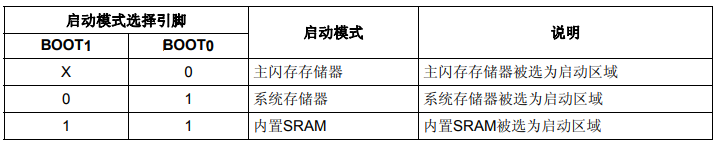
i. When using JTAG\SWD and normal operation, we use the first method (x,0)
ii. The bootloader is preset in the system memory, which can be used for ISP download, which is our commonly used serial port burning
iii. The third method is often used for debugging, and the program can be directly debugged after writing the program into the SRAM. Sub-debugging is very convenient and fast, but the data will be cleared after the SRAM is powered on again, that is to say, the written program can only be used once.
4. Reset circuit
The reset circuit sends a reset signal to the reset pin of the microcontroller under certain conditions (usually pulled low to enable)
Second, the smallest system example
1.STM32F103C8T6 minimum system
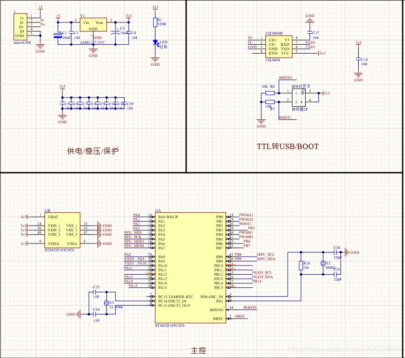
3. Brief analysis of each part
1. Power supply circuit design
The commonly used source of power for microcontrollers is USB or 3.7v lithium battery. The USB voltage is 5v. The discharge voltage range of 3.7v lithium battery is 2.5v~4.2v, while the power supply voltage required by STM32 is 3.3v. , Then we need to design a step-down and voltage stabilization circuit to obtain a voltage of 3.3v. In the smallest system, AMS1117-3.3v forward buck regulator is often used as the main component of processing power,
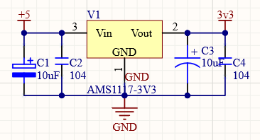
where C1 and C2 are input capacitors to prevent interruption. Voltage inversion occurs after power-on. C3 and C4 are filter capacitors, which suppress self-oscillation and stabilize the output voltage.
2. Principle of external crystal oscillator
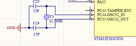
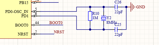
The PC14 and PC15 of the single-chip microcomputer are connected to the external low-speed clock, and the 32.768KHZ crystal oscillator is used (the crystal oscillator inside the quartz watch is also at this frequency. As for why it is not a decimal integer, this is related to the hexadecimal conversion), PD0 and PD1 are connected to the external high-speed clock. 8MHZ crystal oscillator. In the case of not using an external clock, these four pins can be used as normal IO ports. When using a three-pin crystal oscillator and a four-pin crystal oscillator, you can only connect the input part of the pin.
The external clock inside the microcontroller There is a non-gate (Pierce oscillator) with a large gain between the pin input and output, and R10 is a feedback resistor to ensure that the non-gate works in the linear working area, so that the crystal oscillator is easier to start-up. The capacitor is a matching capacitor. The 32.768KHZ is generally 12.5PF, and the 8M is 20-30PF. The matching capacitors recommended by different microcontrollers may not be consistent. For details, see the electrical properties section in the manual.
3. BOOT design
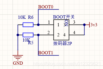
Here is the use of the switch to manually select the high and low levels of BOOT0 and BOOT1.
There are many other connections, such as using jumper caps, buttons, etc.
Because BOOT0=1, BOOT1=1, this startup method is not commonly used, in In the case of selecting high and low levels by the button method, BOOT1 is generally grounded when drawing the circuit, BOOT0 is set to 0 by default, and BOOT0 is set to 1 when the button is pressed.
4. Reset circuit design
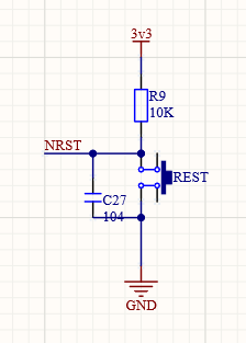
The reset circuit is well understood here.When the button is pressed, the low level of the microcontroller's pin is enabled to trigger the reset.
Reference article: http://www.elecfans.com/article/83/144/2018/20180724714561.html
https://blog.csdn.net/guohengsheng3882/article/details/78175319