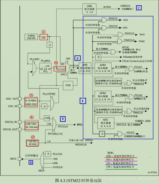
1. Clock system block diagram
![]()
In
STM32
, there are five clock sources,
HSI
,
HSE
,
LSI
,
LSE
,
PLL
. From the clock frequency, it can be divided into high-speed clock source and low-speed clock source. Among these
five
,
HIS
,
HSE
and
PLL
are high-speed clocks, and
LSI
and
LSE
are low -speed clocks.
bell. The slave source can be divided into an external clock source and an internal clock source. The external clock source is a clock source obtained from the outside by connecting to a crystal oscillator. Among them,
HSE
and
LSE
are external clock sources, and the others are internal clock sources. Let's take a look at
the 5 hours of
STM32
Zhong Yuan, the order of our explanation is the order indicated by the red circle in the picture:
①,
HSI
is a high-speed internal clock,
RC
oscillator, the frequency is
8MHz
.
② The
HSE
is a high-speed external clock, which can be connected to a quartz
/
ceramic resonator or an external clock source. The frequency range is
4MHz~16MHz
.
Our development board is connected to an
8M
crystal oscillator.
③
LSI
is a low-speed internal clock,
RC
oscillator, the frequency is
40kHz
. The clock source of the independent watchdog can only be
LSI
, the same
The
LSI
can also be used as
the clock source of the
RTC
.
④
LSE
is a low-speed external clock, connected to
a quartz crystal with a frequency of
32.768kHz
. This is mainly
the clock source of
RTC
.
⑤
PLL
is a phase-locked loop frequency multiplication output, and its clock input source can be selected as
HSI/2
,
HSE
or
HSE/2
. The multiplication frequency can be selected from
2 to 16
times, but the maximum output frequency should not exceed
72MHz
.
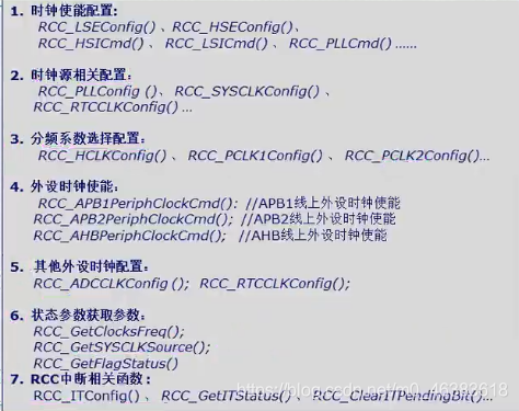
2. RCC related header files and firmware library source files
![]()
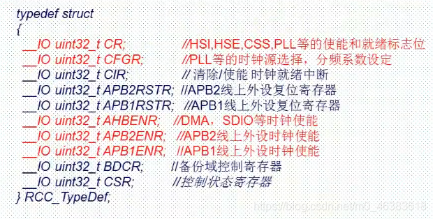
Three, RCC related configuration registers
![]()