The previous review: linux network management actual combat -> theory
Article Directory
linux network management actual combat -> middle chapter
Physical layer
signal
- Signal classification:
Analog signal
Changing physical quantities, usually applicable to changing telephone networks
Digital signal
Two constant physical quantities -> discrete pulse signals, suitable for computer networks, anti-interference and anti-attenuation
medium
- Twisted pair (EIA/TIA568 standard):
shape:
Eight cores, twisted in pairs
Icon:

Function classification:
Shielded and unshielded
Rate classification:
cat 5, Category 5 line
interface:
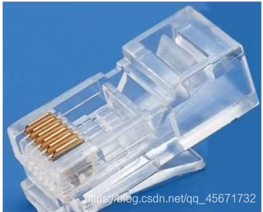
-
optical fiber
Multi-mode, single-mode
Thick core, thin core
Low speed and high speed
data link layer
address
- MAC address
The address of the computer in the local area network is called the MAC address (media access control address)
- structure
There are 48 binary digits---->12 hexadecimal digits
-
Example:
The first six digits are the manufacturer logo, and the last six digits are the hardware logo
You can enter in the command line in centos7
ip a
To view the MAC address
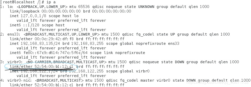
The MAC address of the machine is 52:54:00:b1:12:c1, and the MAC address should be written on the message for encapsulation
Frame encapsulation
Data link layer encapsulation, how is the MAC address written into the information?
The data link layer is encapsulated as follows: target MAC//source MAC//type//data//CRC
CRC is a cyclic redundancy checksum, and CRC ensures data integrity.
How the switch works
- The first step: learning
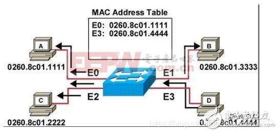
The middle part of the figure is the switch. The switch has many interfaces and connects to multiple computers. The switch will record the information sent by the computer in the MAC Address Table. In this table, the MAC addresses will correspond to the interfaces one by one. , This is the learning of the switch, learning the MAC address and interface of the computer.
- Step 2: Broadcast
In addition to the original port, the information is diffused (addressed). That is, A sent the message to let C know that the switch will send the message to the three computers BCD first, B and D think this message is sent to C, B and D ignore (discard the received message) In the same way, C receives the transfer from A to the switch (the final destination is C), and C replies to A. When C responds to A, the switch will record C's MAC address and interface in the MAC address table
- Step 3: Unicast
After the communication between A and C is completed, they will communicate again. At this time, the switch will find a single channel for them, and let A and C communicate by themselves, so that it will not affect B and D
- Step 4: Update
What happens if there is no communication between computers for a long time?
If the MAC address does not communicate within 300s, it will be erased. This can save the length of the MAC address table (too many MAC addresses, the switch will be very tired), and
the working principle of the switch will be recorded again when communicating again. Getting up is learning, broadcasting, unicasting, and updating.
This is the general principle of the switch.
Build a local area network
The first experiment: a client and a server communicate
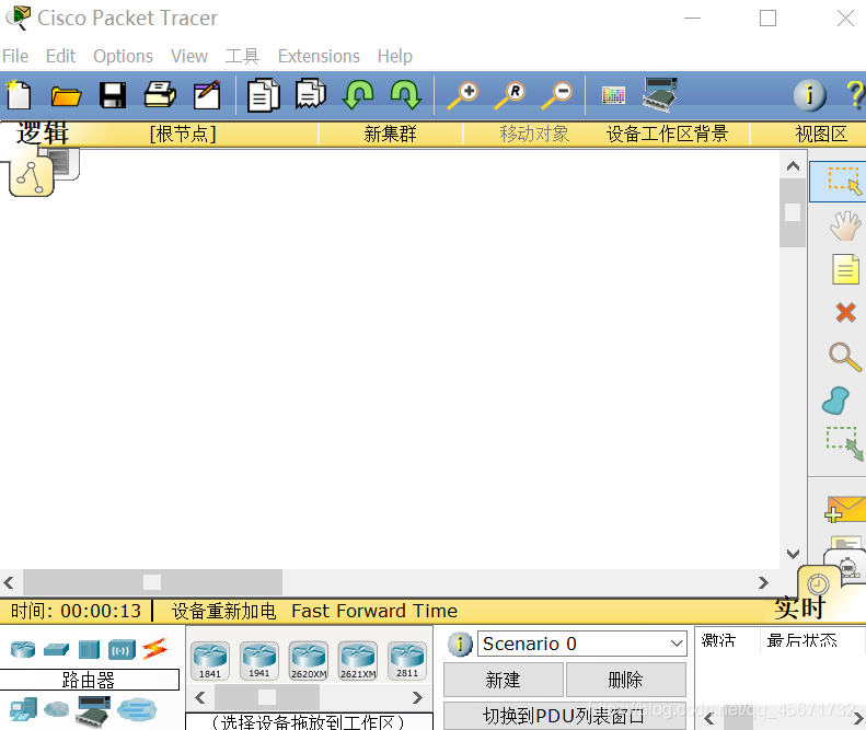
- Install Cisco Packet Tracer software and localize
Build a local area network by yourself, and build a local area network through the Cisco Packet Tracer software.
Cisco Packet Tracer software
extraction code: fiok
decompresses the compressed package, and the next step is to install it. Because the language of the software just entered is English, the software must be Chineseized
. Find the properties in the desktop shortcut and find its installation location
D:\mysoft\Cisco Packet Tracer6.0\Cisco Packet Tracer 6.0\
Find the languages folder, and move the decompressed ptl file to this folder after the stand-alone computer enters.
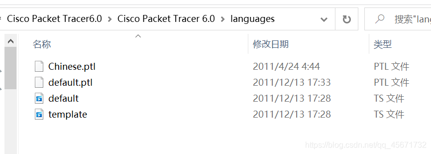
Go back to the software and find the first preferences in the options, select the Chinese language pack, and then apply And re-enter the software.
The localization of the software is complete.
- Actual operating software
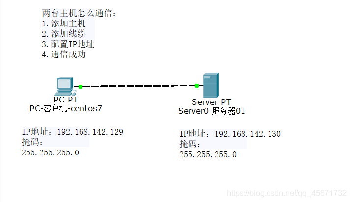
1) Add a host: drag and drop a desktop and a server
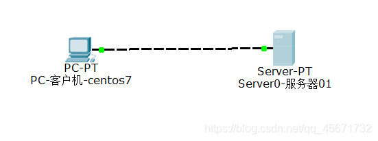
2) Add a cable: connect the cables on the two machines
3) Configure the IP address and sub-mask:
click the desktop and the server, respectively, on the desktop Option has IP address configuration
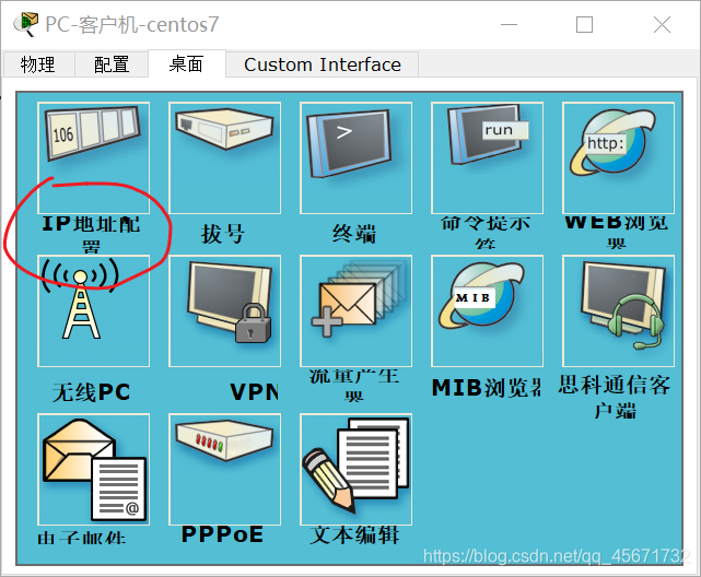
Click to configure the IP and mask. Here I configure the client of centos701 as IP: 192.168.142.129, the sub-mask is: 255.255.255.0 and
the server is configured as IP: 192.168.142.130, the sub-mask is: 255.255.255.0
so that the client and server are configured
4) How to prove that the configuration is successful?
Test communication
There is a command prompt on the desktop of the server or client.
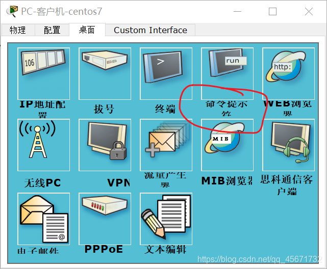
Click it and use the code test:
I use the client's prompt to test:
ping 192.168.142.130
It should be noted that the IP address here is the IP address of the server. Take a small notebook and write it down (when pinging, if the IP address of your client is correct, it does not mean that the communication is successful. Only ping someone else’s server can get it. The result is correct, which can prove that the two machines are communicating.)
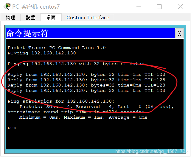
Seeing this, the result of the communication is correct, which proves that the communication was successful.
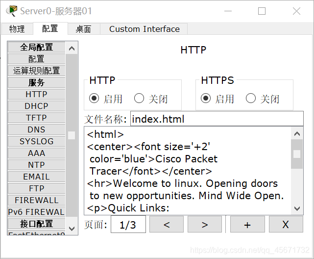
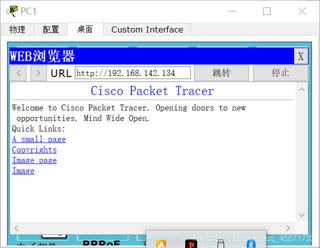
Server 01 can simulate a website and provide web services. You can find HTTP in the configuration of the server, just change index.html, I changed it to linux here
Use the client's centos701 web browser to browse the server's IP address, what will you see?
Type in the search box
http://192.168.142.130
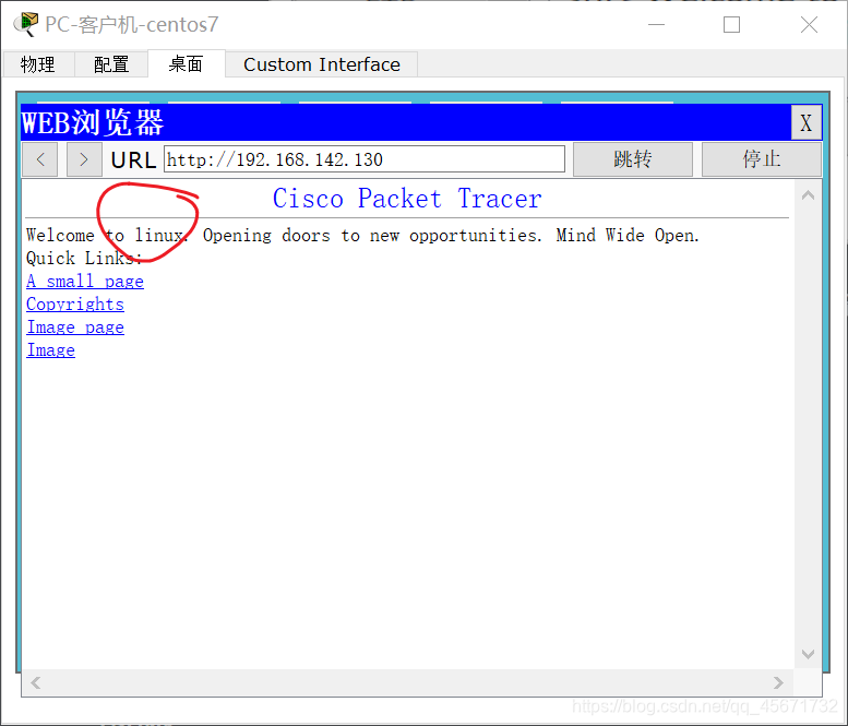
You will see the simulated website of Server 01, proving that the two machines can communicate.
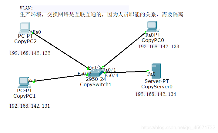
The second experiment: three clients communicate with one server
1) Add three clients and a server, and connect them with a switch
2) Connect cables
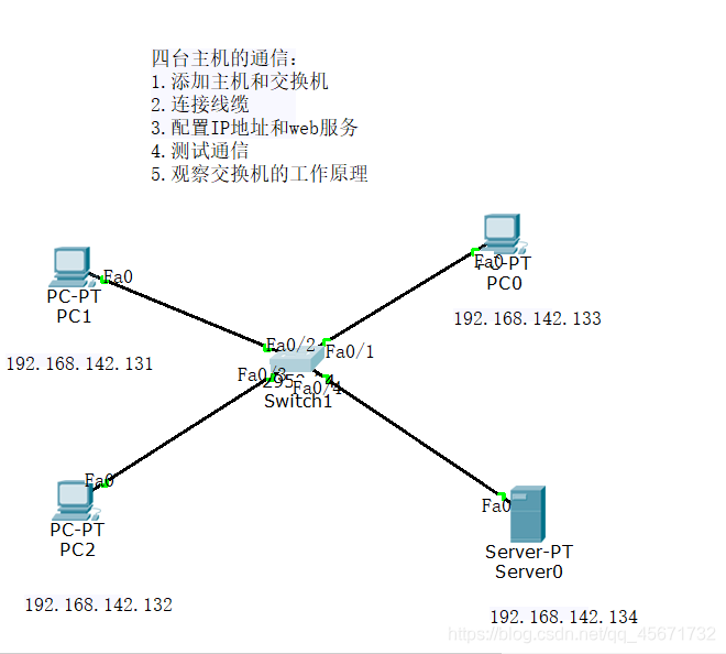
3) Configure the IP address and web service
. As in the previous experiment, configure the IP address and sub-mask in the IP address configuration on the desktop of the client and server.
4) After the test communication
configuration is completed, use a client on the command line Write the following commands in:
ping 192.168.142.131
ping 192.168.142.132
ping 192.168.142.133
ping 192.168.142.134
That is, use the ping command to test the IP address of the machine and observe whether it is successful.
5) Observe the working principle of the
switch : find the command line of the switch -> IOS
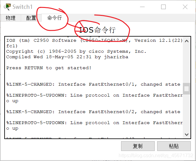
command line and enter it in the command line
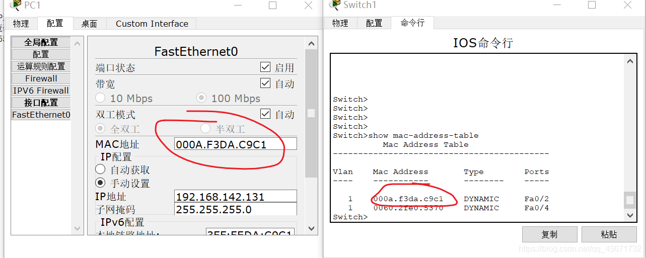
show mac-address-table
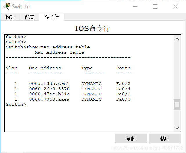
The MAC address table is displayed on the command line of the switch. You can find the corresponding client according to the port number and query the client's MAC address
You can also access the server’s website in a client’s web browser.
After a period of time, go to the switch’s command line and enter
show mac-address-table
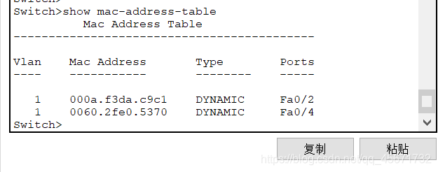
You will see the original table with four pieces of information, but now there are only two tables. Why?
This is because there is no communication for a period of time, and the switch discards the MAC address.
VLAN-->The soul of the switch
- VLAN explanation
VLAN (abbreviation of Virtual Local Area Network) Chinese name: Virtual Local Area Network.
- Diagram In the
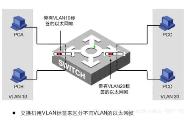
diagram, A and B are a group, and C and D are a group of
VLAN to ensure that while A and B, C and D communicate, A and C, B and D cannot communicate. - Method of dividing VLAN
1) Create a VLAN
VLAN is a segment of numbers, among which 0 and 1 have been requisitioned, ranging from 2 to 1024 (this is the regulation)
2) According to the relationship between the interface and the VLAN,
separated by ports, the interface of the switch is the key to dividing VLAN .
such as:
F0/1–>F0/10 VLAN 10
F0/11–>F0/20 VLAN 20
- Configuration
1) First configure on the switch, enter the following code in the switch command line:
  enable # 特权
  config t # 进入配置模式(config)
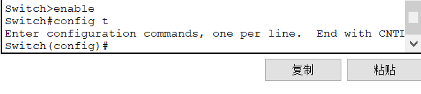
At this time, enter the following code in the command line:
vlan 10 # 创建局域网10
vlan 20 # 创建局域网20
interface fastethernet0/1 # 必须要在接口模式下才可以输入,或者时int f0/1
switch access vlan 10 # 将端口加入VLAN
In this way, f0/1 joins the LAN 10.
Use the same method to add f0/2 to the LAN 10, add f0/3 and f0/4 to the LAN 20.
Enter the privileged mode, enter show vlan, and view the vlan information.
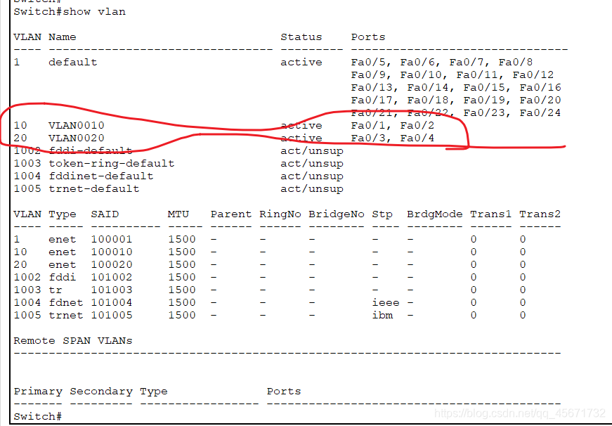
It can be clearly seen that f0/1 and f0/2 are in VLAN 10, and f0/3 and f0/4 are in VLAN 20.
How to prove that it has been allocated?
You can find a client and use the ping command in the client's command line to verify whether the communication is successful. If it is unsuccessful, an error (timeout) will be reported.
You can also use a web browser to access the IP address of another host to verify.
In this way, hosts in the same group can communicate without fear of being stolen.
Trunk
- Trunk's core technology
Trunk and VLAN complement each other. Sometimes employees in the same department of a company may not be in the same office or on the same floor, so they still have to communicate. This uses Trunk technology, which means trunk in Chinese. It is a configuration command to accomplish one thing: to transmit multiple VLAN information on the same cable (not to be messy). So what is the principle of Trunk? Trunk is to label VLANs one by one. For example, if two switches are connected to multiple computers, employees of the same department on different floors will exchange information, and the information of the same department will first be tagged with a VLAN label. When arriving at the switch, the switch will first identify the vlan information label, and then decide the destination of the information, which allows the same department on different floors to exchange information, but different departments cannot exchange information. - The
first step of the experiment Trunk : Configuration
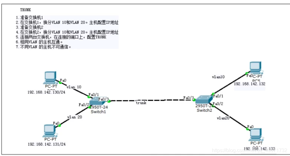
Enter the following commands in the IOS command line of the switch (the port numbers must be consistent)
en
config t
vlan 10
vlan 20
int f0/1
sw ac vlan 10
int f0/2
sw ac vlan 20
int f0/3
switch mode trunk
- The theoretical experimental results
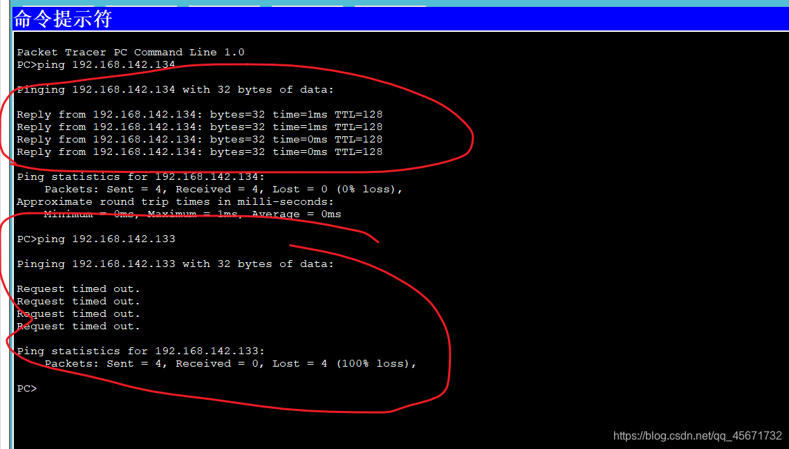
130 and 132 are the same vlan can communicate, 131 and 133 are the same vlan can communicate.
130 and 133 cannot communicate, and 131 and 132 cannot communicate. - Test the experimental results
You can test on the command line or web browser on each machine to verify the theoretical experimental results.
The vlan label only exists in the Trunk link.