本文内容转载自:《404blog》
在内核启动前,bootloader做如下准备工作:
- CPU寄存器:R0 = 0、R1 = 机器码(linux/arch/tools/mach-types)、R2 = tags在RAM中的物理地址
- CPU和MMU:SVC模式,禁止中断,MMU关闭,数据Cache关闭。
(一)自解压分析
在该阶段主要完成的工作有:
- 1.保存机器码和启动参数到r7和r8寄存器中
- 2.设置CPU为SVC工作模式
- 3.关闭中断
- 4.获取内核解压地址保存到r4寄存器中
- 5.开启缓存和MMU
- 6.判断内核解压地址空间和当前镜像地址空间是否覆盖
- 7.判断运行地址是否为连接地址
- 8.清除BSS段
- 9.解压内核
- 10.刷新缓存并关闭缓存和MMU
- 11.恢复机器码和启动参数地址到r1和r2寄存器中
- 12.跳转到解压地址运行
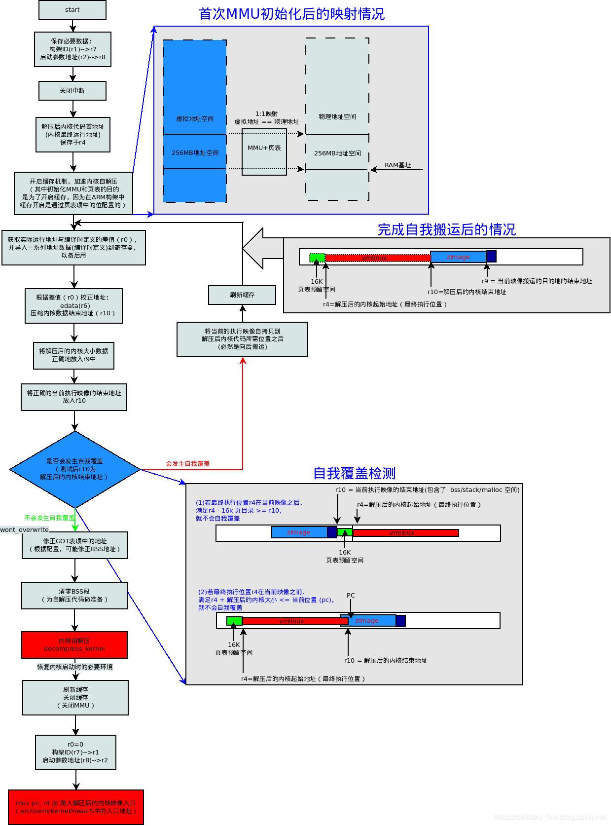
内核自解压部分的总流程如下:

start:
        .type   start,#function
        .rept   7
        mov r0, r0
        .endr
   ARM(     mov r0, r0      )
   ARM(     b   1f      )
 THUMB(     adr r12, BSYM(1f)   )
 THUMB(     bx  r12     )
使用.type标号来指明start的符号类型是函数类型,然后重复执行.rept到.endr之间的指令7次,这里一共执行了7次mov r0, r0指令,共占用了4*7 = 28个字节,这是用来存放ARM的异常向量表的。向前跳转到标号为1处执行:
1:
        mrs r9, cpsr
#ifdef CONFIG_ARM_VIRT_EXT
        bl  __hyp_stub_install  @ get into SVC mode, reversibly
#endif
        mov r7, r1          @ save architecture ID
        mov r8, r2          @ save atags pointer
这里将CPU的工作模式保存到r9寄存器中,将uboot通过r1传入的机器码保存到r7寄存器中,将启动参数tags的地址保存到r8寄存器中。
    /*
     * Booting from Angel - need to enter SVC mode and disable
     * FIQs/IRQs (numeric definitions from angel arm.h source).
     * We only do this if we were in user mode on entry.
     */
    mrs r2, cpsr        @ get current mode
    tst r2, #3          @ not user?
    bne not_angel
    mov r0, #0x17       @ angel_SWIreason_EnterSVC
ARM(        swi 0x123456    )   @ angel_SWI_ARM
THUMB(      svc 0xab        )   @ angel_SWI_THUMB
这里将CPU的工作模式保存到r2寄存器中,然后判断是否是SVC模式,如果是USER模式就会通过swi指令产生软中断异常的方式来自动进入SVC模式。
not_angel:
        safe_svcmode_maskall r0
        msr spsr_cxsf, r9       @ Save the CPU boot mode in
                        @ SPSR
safe_svcmode_maskall是一个宏,定义在arch/arm/include/asm/assembler.h中:
/*
 * Helper macro to enter SVC mode cleanly and mask interrupts. reg is
 * a scratch register for the macro to overwrite.
 *
 * This macro is intended for forcing the CPU into SVC mode at boot time.
 * you cannot return to the original mode.
 */
.macro safe_svcmode_maskall reg:req
#if __LINUX_ARM_ARCH__ >= 6
    mrs \reg , cpsr
    eor \reg, \reg, #HYP_MODE
    tst \reg, #MODE_MASK
    bic \reg , \reg , #MODE_MASK
    orr \reg , \reg , #PSR_I_BIT | PSR_F_BIT | SVC_MODE
THUMB(  orr \reg , \reg , #PSR_T_BIT    )
    bne 1f
    orr \reg, \reg, #PSR_A_BIT
    adr lr, BSYM(2f)
    msr spsr_cxsf, \reg
    __MSR_ELR_HYP(14)
    __ERET
1:  msr cpsr_c, \reg
2:
#else
/*
 * workaround for possibly broken pre-v6 hardware
 * (akita, Sharp Zaurus C-1000, PXA270-based)
 */
    setmode PSR_F_BIT | PSR_I_BIT | SVC_MODE, \reg
#endif
.endm
这里的注释已经说明了,这里是强制将CPU的工作模式切换到SVC模式,并且关闭IRQ和FIQ中断。然后将r9中保存的原始CPU配置保存到SPSR中。
#ifdef CONFIG_AUTO_ZRELADDR
        @ determine final kernel image address
        mov r4, pc
        and r4, r4, #0xf8000000
        add r4, r4, #TEXT_OFFSET
#else
        ldr r4, =zreladdr
#endif
内核配置项AUTO_ZRELDDR表示自动计算内核解压地址(Auto calculation of the decompressed kernelimage address),这里没有选择这个配置项,所以保存到r4中的内核解压地址就是zreladdr,这个参数在linux/arch/arm/boot/compressed/Makefile中:
ifneq ($(CONFIG_AUTO_ZRELADDR),y)
LDFLAGS_vmlinux += --defsym zreladdr=$(ZRELADDR)
endif
而ZRELADDR定义在arch/arm/boot/Makefile中:
ifneq ($(MACHINE),)
include $(srctree)/$(MACHINE)/Makefile.boot
endif

# Note: the following conditions must always be true:
#   ZRELADDR == virt_to_phys(PAGE_OFFSET + TEXT_OFFSET)
#   PARAMS_PHYS must be within 4MB of ZRELADDR
#   INITRD_PHYS must be in RAM
ZRELADDR    := $(zreladdr-y)
PARAMS_PHYS := $(params_phys-y)
INITRD_PHYS := $(initrd_phys-y)
既然看到了内核解压地址zreladdr,也顺便来看一下params_phys和initrd_phys的值,他们最终由arch/arm/mach-$(SOC)/Makefile.boot决定,我们这里用S3C24XX,他的Makefile.boot内容如下:
ifeq ($(CONFIG_PM_H1940),y)
    zreladdr-y    += 0x30108000
    params_phys-y    := 0x30100100
else
    zreladdr-y    += 0x30008000
    params_phys-y    := 0x30000100
endif
这里的params_phys-y和initrd_phys-y是内核参数的物理地址和initrd文件系统的物理地址。其实除了zreladdr外这些地址uboot都会传入的。
/*
 * Set up a page table only if it won't overwrite ourself.
 * That means r4 < pc && r4 - 16k page directory > &_end.
 * Given that r4 > &_end is most unfrequent, we add a rough
 * additional 1MB of room for a possible appended DTB.
 */
mov r0, pc
cmp r0, r4
ldrcc   r0, LC0+32
addcc   r0, r0, pc
cmpcc   r4, r0
orrcc   r4, r4, #1      @ remember we skipped cache_on
blcs    cache_on
这里将比较当前PC地址和内核解压地址,只有在不会自覆盖的情况下才会创建一个页表,如果当前运行地址PC小于解压地址r4,则读取LC0+32地址处的内容加载到r0中,否则跳转到cache_on处执行缓存初始化和MMU初始化。LC0是地址表,定义在525行:
        .align  2  w
        .type   LC0, #object
LC0:        .word   LC0         @ r1
        .word   __bss_start     @ r2
        .word   _end            @ r3
        .word   _edata          @ r6  :i
        .word   input_data_end - 4  @ r10 (inflated size location)
        .word   _got_start      @ r11
        .word   _got_end        @ ip
        .word   .L_user_stack_end   @ sp
        .word   _end - restart + 16384 + 1024*1024
        .size   LC0, . - LC0
LC0+32地址处的内容为:_end -restart + 16384 + 10241024,所指的就是程序长度+16k的页表长+1M的DTB空间。继续比较解压地址r4(0x00008000)和当前运行程序的(结束地址+16384 + 10241024),如果小于则不进行缓存初始化并置位r4最低位进行标识。总的来说就是这样:
- PC >= r4:直接进行缓存初始化
- PC < r4 && _end + 16384+ 1024*1024 > r4:不进行缓存初始化
- PC < r4 && _end + 16384+ 1024*1024 <= r4:执行缓存初始化
这里先暂时不分析cache_on(已补充在文中最后分析),继续沿主线往下分析:
restart:    adr r0, LC0
        ldmia   r0, {r1, r2, r3, r6, r10, r11, r12}
        ldr sp, [r0, #28]
通过前面LC0地址表的内容可见,这里r0中的内容就是编译时决定的LC0的实际运行地址(特别注意不是链接地址),然后调用ldmia命令依次将LC0地址表处定义的各个地址加载到r1、r2、r3、r6、r10、r11、r12和SP寄存器中去。执行之后各个寄存器中保存内容的意义如下:
- r0:LC0标签处的运行地址
- r1:LC0标签处的链接地址
- r2:__bss_start处的链接地址
- r3:_ednd处的链接地址(即程序结束位置)
- r6:_edata处的链接地址(即数据段结束位置)
- r10:压缩后内核数据大小位置
- r11:GOT表的启示链接地址
- r12:GOT表的结束链接地址
- sp:栈空间结束地址 195~196行这段代码通过反汇编来看着部分代码会更加清晰(反汇编arch/arm/boot /compressed/vmlinux):
000000c0 <restart>:
    c0:   e28f0e13    add r0, pc, #304    ; 0x130
    c4:   e8901c4e    ldm r0, {r1, r2, r3, r6, sl, fp, ip}
    c8:   e590d01c    ldr sp, [r0, #28]
由于实际的运行在物理地址为0x00008000处,所以r0 = pc + 0x130 = 0x00008000 + 0xc0 + 0x8 + 0x130 = 0x00008000 +0x1F8,而0x000081F8物理地址处的内容就是LC0:
000001f8 <LC0>:
   1f8:   000001f8    strdeq  r0, [r0], -r8
   1fc:   006f2a80    rsbeq   r2, pc, r0, lsl #21
   200:   006f2a98    mlseq   pc, r8, sl, r2  ; <UNPREDICTABLE>
   204:   006f2a80    rsbeq   r2, pc, r0, lsl #21
   208:   006f2a45    rsbeq   r2, pc, r5, asr #20
   20c:   006f2a58    rsbeq   r2, pc, r8, asr sl  ; <UNPREDICTABLE>
   210:   006f2a7c    rsbeq   r2, pc, ip, ror sl  ; <UNPREDICTABLE>
   214:   006f3a98    mlseq   pc, r8, sl, r3  ; <UNPREDICTABLE>
   218:   007f69d8    ldrsbteq    r6, [pc], #-152
   21c:   e320f000    nop {0}
在获取了LC0的链接地址和运行地址后,就可以通过计算这两者之间的差值来获得当前行的地址是否就是编译时的链接地址。
/*
 * We might be running at a different address.  We need
 * to fix up various pointers.
 */
sub r0, r0, r1      @ calculate the delta offset
add r6, r6, r0      @ _edata
add r10, r10, r0        @ inflated kernel size location
将运行地址和链接地址的偏移保存到r0寄存器中,然后更新r6和r10中的地址,将其转换为实际的运行地址。
/*
 * The kernel build system appends the size of the
 * decompressed kernel at the end of the compressed data
 * in little-endian form.
 */
ldrb    r9, [r10, #0]
ldrb    lr, [r10, #1]
orr r9, r9, lr, lsl #8
ldrb    lr, [r10, #2]
ldrb    r10, [r10, #3]
orr r9, r9, lr, lsl #16
orr r9, r9, r10, lsl #24
注释中说明了,内核编译系统在压缩内核时会在末尾处以小端模式附上未压缩的内核大小,这部分代码的作用就是将该值计算出来并保存到r9寄存器中去。
#ifndef CONFIG_ZBOOT_ROM
        /* malloc space is above the relocated stack (64k max) */
        add sp, sp, r0
        add r10, sp, #0x10000
#else
        /*
         * With ZBOOT_ROM the bss/stack is non relocatable,
         * but someone could still run this code from RAM,
         * in which case our reference is _edata.
         */
        mov r10, r6
#endif
这里将镜像的结束地址保存到r10中去,如果定义了ZBOOT_ROM则bss和stack是非可重定位的,这里将r10设置为sp结束地址上64kb处(这64kB空间是用来作为堆空间的)。 接下来内核如果配置为支持设备树(DTB)会做一些特别的工作,先跳过。
/*
 * Check to see if we will overwrite ourselves.
 *   r4  = final kernel address (possibly with LSB set)
 *   r9  = size of decompressed image
 *   r10 = end of this image, including  bss/stack/malloc space if non XIP
 * We basically want:
 *   r4 - 16k page directory >= r10 -> OK
 *   r4 + image length <= address of wont_overwrite -> OK
 * Note: the possible LSB in r4 is harmless here.
 */
        add r10, r10, #16384
        cmp r4, r10
        bhs wont_overwrite
        add r10, r4, r9
        adr r9, wont_overwrite
        cmp r10, r9
        bls wont_overwrite
这里r4、r9和r10中的内容见注释。这部分代码用来分析当前代码是否会和最后的解压部分重叠,如果有重叠则需要执行代码搬移。首先比较内核解压地址r4-16Kb(这里是0x00004000,包括16KB的内核页表存放位置)和r10,如果r4 – 16kB >= r10,则无需搬移,否则继续计算解压后的内核末尾地址是否在当前运行地址之前,如果是则同样无需搬移,不然的话就需要进行搬移了。
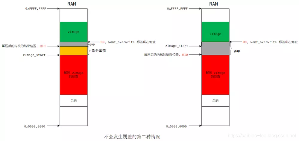
总结一下可能的3种情况:
- 内核起始地址– 16kB >= 当前镜像结束地址:无需搬移
- 内核结束地址 <= wont_overwrite运行地址:无需搬移
- 内核起始地址– 16kB < 当前镜像结束地址 && 内核结束地址 > wont_overwrite运行地址:需要搬移
仔细分析一下,这里内核真正运行的地址是0x00004000,而现在代码的运行地址显然已经在该地址之后了,反汇编发现wont_overwrite的运行地址是0x00008000+0x00000168),而且内核解压后的空间必然会覆盖掉这里(内核解压后的大小大于0x00000168),所以这里会执行代码搬移。
/*
 * Relocate ourselves past the end of the decompressed kernel.
 *   r6  = _edata
 *   r10 = end of the decompressed kernel
 * Because we always copy ahead, we need to do it from the end and go
 * backward in case the source and destination overlap.
 */
        /*
         * Bump to the next 256-byte boundary with the size of
         * the relocation code added. This avoids overwriting
         * ourself when the offset is small.
         */
        add r10, r10, #((reloc_code_end - restart + 256) & ~255)
        bic r10, r10, #255

        /* Get start of code we want to copy and align it down. */
        adr r5, restart
        bic r5, r5, #31
从这里开始会将镜像搬移到解压的内核地址之后,首先将解压后的内核结束地址进行扩展,扩展大小为代码段的大小(reloc_code_end定义在head.s的最后)保存到r10中,即搬运目的起始地址,然后r5保存了restart的起始地址,并进行对齐,即搬运的原起始地址。反汇编查看这里扩展的大小为0x800:
11c:    e28aab02    add sl, sl, #2048   ; 0x800
120:    e3caa0ff    bic sl, sl, #255    ; 0xff
124:    e24f506c    sub r5, pc, #108    ; 0x6c
128:    e3c5501f    bic r5, r5, #31
sub r9, r6, r5 @ size to copy
add r9, r9, #31 @ rounded up to a multiple
bic r9, r9, #31 @ ... of 32 bytes
add r6, r9, r5
add r9, r9, r10
1: ldmdb r6!, {r0 - r3, r10 - r12, lr}
cmp r6, r5
stmdb r9!, {r0 - r3, r10 - r12, lr}
bhi 1b
/* Preserve offset to relocated code. */
sub r6, r9, r6
#ifndef CONFIG_ZBOOT_ROM
/* cache_clean_flush may use the stack, so relocate it */
add sp, sp, r6
#endif 这里首先计算出需要搬运的大小保存到r9中,搬运的原结束地址到r6中,搬运的目的结束地址到r9中。注意这里只搬运代码段和数据段,并不包含bss、栈和堆空间。 接下来开始执行代码搬移,这里是从后往前搬移,一直到r6 == r5结束,然后r6中保存了搬移前后的偏移,并重定向栈指针(cache_clean_flush可能会使用到栈)。
    bl  cache_clean_flush

    adr r0, BSYM(restart)
    add r0, r0, r6
    mov pc, r0
首先调用cache_clean_flush清楚缓存,然后将PC的值设置为搬运后restart的新地址,然后重新从restart开始执行。这次由于进行了代码搬移,所以会在检查自覆盖时进入wont_overwrite处执行。
wont_overwrite:
/*
 * If delta is zero, we are running at the address we were linked at.
 *   r0  = delta
 *   r2  = BSS start
 *   r3  = BSS end
 *   r4  = kernel execution address (possibly with LSB set)
 *   r5  = appended dtb size (0 if not present)
 *   r7  = architecture ID
 *   r8  = atags pointer
 *   r11 = GOT start
 *   r12 = GOT end
 *   sp  = stack pointer
 */
        orrs    r1, r0, r5
        beq not_relocated
这里的注释列出了现有所有寄存器值得含义,如果r0为0则说明当前运行的地址就是链接地址,无需进行重定位,跳转到not_relocated执行,但是这里运行的地址已经被移动到内核解压地址之后,显然不会是链接地址0x00000168(反汇编代码中得到),所以这里需要重新修改GOT表中的变量地址来实现重定位。
    add r11, r11, r0
    add r12, r12, r0

#ifndef CONFIG_ZBOOT_ROM
    /*
     * If we're running fully PIC === CONFIG_ZBOOT_ROM = n,
     * we need to fix up pointers into the BSS region.
     * Note that the stack pointer has already been fixed up.
     */
    add r2, r2, r0
    add r3, r3, r0
这里更新GOT表的运行起始地址到r11和结束地址到r12中去,然后同样更新BSS段的运行地址(需要修正BSS段的指针)。接下来开始执行重定位:
    /*
     * Relocate all entries in the GOT table.
     * Bump bss entries to _edata + dtb size
     */
1:      ldr r1, [r11, #0]       @ relocate entries in the GOT
    add r1, r1, r0      @ This fixes up C references
    cmp r1, r2          @ if entry >= bss_start &&
    cmphs   r3, r1          @       bss_end > entry
    addhi   r1, r1, r5      @    entry += dtb size
    str r1, [r11], #4       @ next entry
    cmp r11, r12
    blo 1b

    /* bump our bss pointers too */
    add r2, r2, r5
    add r3, r3, r5
通过r1获取GOT表中的一项,然后对这一项的地址进行修正,如果修正后的地址 < BSS段的起始地址,或者在BSS段之中则再加上DTB的大小(如果不支持DTB则r5的值为0),然后再将值写回GOT表中去。如此循环执行直到遍历完GOT表。来看一下反汇编出来的GOT表,加深理解:
006f2a58 <.got>:
    6f2a58:   006f2a49    rsbeq   r2, pc, r9, asr #20
    6f2a5c:   006f2a94    mlseq   pc, r4, sl, r2  ; <UNPREDICTABLE>
    6f2a60:   0000466c    andeq   r4, r0, ip, ror #12
    6f2a64:   006f2a90    mlseq   pc, r0, sl, r2  ; <UNPREDICTABLE>
    6f2a68:   006f2a80    rsbeq   r2, pc, r0, lsl #21
    6f2a6c:   0000090c    andeq   r0, r0, ip, lsl #18
    6f2a70:   006f2a88    rsbeq   r2, pc, r8, lsl #21
    6f2a74:   006f2a8c    rsbeq   r2, pc, ip, lsl #21
    6f2a78:   006f2a84    rsbeq   r2, pc, r4, lsl #21
以这里的6f2a60: 0000466c为例,0000466c为input_data符号的链接地址,定义在arch/arm/boot/compressed/piggy.gzip.S中,可以算作是全局变量,这里在执行重定位时会将6f2a60地址处的值加上偏移,可得到input_data符号的运行地址,以此完成重定位工作,以后在内核的C代码中如果用到input_data符号就从这里的地址加载。
not_relocated:  mov r0, #0
1:      str r0, [r2], #4        @ clear bss
        str r0, [r2], #4
        str r0, [r2], #4
        str r0, [r2], #4
        cmp r2, r3
        blo 1b
在重定位完成后,继续执行not_relocated部分代码,这里循环清零BSS段。
/*
 * Did we skip the cache setup earlier?
 * That is indicated by the LSB in r4.
 * Do it now if so.
 */
tst r4, #1
bic r4, r4, #1
blne    cache_on
这里检测r4中的最低位,如果已经置位则说明在前面执行restart前并没有执行cache_on来打开缓存(见前文),这里补执行。
/*
 * The C runtime environment should now be setup sufficiently.
 * Set up some pointers, and start decompressing.
 *   r4  = kernel execution address
 *   r7  = architecture ID
 *   r8  = atags pointer
 */
        mov r0, r4
        mov r1, sp          @ malloc space above stack
        add r2, sp, #0x10000    @ 64k max
        mov r3, r7
        bl  decompress_kernel
到此为止,C语言的执行环境已经准备就绪,设置一些指针就可以开始解压内核了(这里的内核解压部分是使用C代码写的)。
这里r0~r3的4个寄存器是decompress_kernel()函数传参用的,r0传入内核解压后的目的地址,r1传入堆空间的起始地址,r2传入堆空间的结束地址,r3传入机器码,然后就开始调用decompress_clean_flush()函数执行内核解压操作:
void decompress_kernel(unsigned long output_start, unsigned long free_mem_ptr_p,
        unsigned long free_mem_ptr_end_p,
        int arch_id)
{
    int ret;

    output_data     = (unsigned char *)output_start;
    free_mem_ptr        = free_mem_ptr_p;
    free_mem_end_ptr    = free_mem_ptr_end_p;
    __machine_arch_type = arch_id;

    arch_decomp_setup();

    putstr("Uncompressing Linux...");
    ret = do_decompress(input_data, input_data_end - input_data,
                output_data, error);
    if (ret)
        error("decompressor returned an error");
    else
        putstr(" done, booting the kernel.\n");
}
真正执行内核解压的函数是do_decompress()->decompress()(该函数会根据不同的压缩方式调用不同的解压函数),在解压前会在终端上打印“Uncompressing Linux…”,结束后会打印出“done, booting the kernel.\n”。
    bl  cache_clean_flush
    bl  cache_off
    mov r1, r7          @ restore architecture number
    mov r2, r8          @ restore atags pointer
解压完成后就刷新缓存,然后将缓存(包括MMU关闭),这里之所以要打开缓存和MMU是为了加速内核解压。
然后将机器码和内启动参数atags恢复到r1和r2寄存器中,为跳转到解压后的内核代码做准备。
__enter_kernel:
        mov r0, #0          @ must be 0
 ARM(       mov pc, r4  )       @ call kernel
 THUMB(     bx  r4  )       @ entry point is always ARM
补充:缓存和MMU初始化cache_on的执行流程
     *
     * We place the page tables 16k down from the kernel execution address,
     * and we hope that nothing else is using it.  If we're using it, we
     * will go pop!
     *
     * On entry,
     *  r4 = kernel execution address
     *  r7 = architecture number
     *  r8 = atags pointer
     * On exit,
     *  r0, r1, r2, r3, r9, r10, r12 corrupted
     * This routine must preserve:
     *  r4, r7, r8
     */
            .align  5
    cache_on:   mov r3, #8          @ cache_on function
            b   call_cache_fn
注释中说明了,为了开启I Cache和D Cache,需要建立页表(开启MMU),而页表使用的就是内核运行地址以下的16KB空间(对于我的环境来说地址就等于0x00004000~0x00008000)。同时在运行的过程中r0~r3以及r9、r10和r12寄存器会被使用。
这里首先在r3中保存打开缓存函数表项在cache操作表中的地址偏移(这里为8,cache操作表见后文),然后跳转到call_cache_fn中。
    /*
     * Here follow the relocatable cache support functions for the
     * various processors.  This is a generic hook for locating an
     * entry and jumping to an instruction at the specified offset
     * from the start of the block.  Please note this is all position
     * independent code.
     *
     *  r1  = corrupted
     *  r2  = corrupted
     *  r3  = block offset
     *  r9  = corrupted
     *  r12 = corrupted
     */

    call_cache_fn:  adr r12, proc_types
    #ifdef CONFIG_CPU_CP15
            mrc p15, 0, r9, c0, c0  @ get processor ID
    #else
            ldr r9, =CONFIG_PROCESSOR_ID
    #endif
    1:      ldr r1, [r12, #0]       @ get value
            ldr r2, [r12, #4]       @ get mask
            eor r1, r1, r9      @ (real ^ match)
            tst r1, r2          @       & mask
     ARM(       addeq   pc, r12, r3     ) @ call cache function
     THUMB(     addeq   r12, r3         )
     THUMB(     moveq   pc, r12         ) @ call cache function
            add r12, r12, #PROC_ENTRY_SIZE
            b   1b
首先保存cache操作表的运行地址到r12寄存器中,proc_types定义在head.s中的825行:
     *   - CPU ID match
     *   - CPU ID mask
     *   - 'cache on' method instruction
     *   - 'cache off' method instruction
     *   - 'cache flush' method instruction
     *
     * We match an entry using: ((real_id ^ match) & mask) == 0
     *
     * Writethrough caches generally only need 'on' and 'off'
     * methods.  Writeback caches _must_ have the flush method
     * defined.
     */
            .align  2
            .type   proc_types,#object
表中的每一类处理器都包含以下5项(如果不存在缓存操作函数则使用“mov pc, lr”占位):
- CPU ID
- CPU ID 位掩码(用于匹配CPU类型用)
- 打开缓存“cache on”函数入口
- 关闭缓存“cache off”函数入口
- 刷新缓存“cache flush”函数入口
其中我环境中使用到的ARMv6的cache操作表如下:
    .word   0x0007b000      @ ARMv6
    .word   0x000ff000
    W(b)    __armv6_mmu_cache_on
    W(b)    __armv4_mmu_cache_off
    W(b)    __armv6_mmu_cache_flush
我的环境中由于配置了CPU_CP15条件编译项,所以这里将从CP15中获取CPU型号而不是从内核配置项中获取。
然后逐条对cache操作表中的CPU类型进行匹配,如果匹配上了就跳转到相应的函数入口执行。
这里通过反汇编代码来理解一下:
0000044c <call_cache_fn>:
     44c:   e28fc01c    add ip, pc, #28
     450:   ee109f10    mrc 15, 0, r9, cr0, cr0, {0}
     454:   e59c1000    ldr r1, [ip]
     458:   e59c2004    ldr r2, [ip, #4]
     45c:   e0211009    eor r1, r1, r9
     460:   e1110002    tst r1, r2
     464:   008cf003    addeq   pc, ip, r3
     468:   e28cc014    add ip, ip, #20
     46c:   eafffff8    b   454 <call_cache_fn+0x8>
这里首先在r12中获取了proc_types的运行地址:pc + 0x8 + 0x1c:
然后逐条匹配,最后会匹配到ARMv6部分,cache table中ARMv6部分的代码如下:
    5b0:    0007b000    andeq   fp, r7, r0
    5b4:    000ff000    andeq   pc, pc, r0
    5b8:    eaffff5c    b   330 <__armv6_mmu_cache_on>
    5bc:    ea00001f    b   640 <__armv4_mmu_cache_off>
    5c0:    ea00004f    b   704 <__armv6_mmu_cache_flush>
于是PC寄存器就执行上面5b8地址处的内容,这条机器码被翻译为相对跳转到__armv6_mmu_cache_on处执行:
00000330 <__armv6_mmu_cache_on>: 这样__armv6_mmu_cache_on就被调用执行了。
__armv6_mmu_cache_on中会通过写寄存器来开启MMU、I Cache和D Cache,这里具体就不仔细分析了,其中为MMU建立页表有必要分析一下:
前文已经分析过在内核最终运行地址r4下面有16KB的空间(我环境中是0x00004000~0x00008000),这就是用来存放页表的,但是现在要建立的页表在内核真正启动后会被销毁,只是用于零时存放。同时这里将要建立的页表映射关系是1:1映射(即虚拟地址 == 物理地址)。
__setup_mmu:    sub r3, r4, #16384      @ Page directory size
        bic r3, r3, #0xff       @ Align the pointer
        bic r3, r3, #0x3f00
首先在r3中保存的是页目录表的基地址,需要将低14位清零进行16KB对齐。
    /*
    * Initialise the page tables, turning on the cacheable and bufferable
    * bits for the RAM area only.
    */
    mov r0, r3
    mov r9, r0, lsr #18
    mov r9, r9, lsl #18     @ start of RAM
    add r10, r9, #0x10000000    @ a reasonable RAM size
这里建立页表,只对物理RAM空间建立cache和buffer。然后通过将r0(r3)中的地址值右移18位再左移18位(即清零r3中地址的低18位),得到物理RAM空间的“初始地址”(R9 = PHY_OFFSET) 并保存到r9(0x00000000)中去,然后将该地址加上256MB的大小作为物理RAM的“结束地址”(也是估计值)并保存到r10(0x10000000)中去。这里的另一个隐含意思也就是最多映射256MB大小的空间。
mov r1, #0x12 @ XN|U + section mapping
orr r1, r1, #3 << 10 @ AP=11
add r2, r3, #16384
cmp r1, r9 @ if virt > start of RAM
cmphs r10, r1 @ && end of RAM > virt
bic r1, r1, #0x1c @ clear XN|U + C + B
orrlo r1, r1, #0x10 @ Set XN|U for non-RAM
orrhs r1, r1, r6 @ set RAM section settings
str r1, [r0], #4 @ 1:1 mapping
add r1, r1, #1048576
teq r0, r2
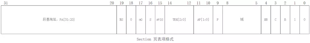
bne 1b ARM11的MMU支持两级分页机制,用户通过配置TTBCR可选映射方式,这里只采用一级映射方式,每页的大小为1MB,4GB线性空间占4096个表项。ARM手册中列出了映射的关系如下:
其中TTB的值就是页表存放的起始地址值0x00004000。这里虚拟地址转换到物理地址的方式如下:首先将虚拟地址的高12位(页表中的索引)左移2位(正好为14位长度,补齐Translation table base中低14位的空白)得到在页表中的偏移地址,该偏移值加上页表基地址就得到了对应表项的物理地址,然后取出表项中的高12位值作为物理地址的基地址,最后以虚拟地址的低20位作为偏移地址值就得到了最终映射后的物理地址。
这里First-level descriptor中的内容就是这里程序中要填充的值,其中最低2位为0b10表示表项中保存的是Section base address,而不是2级页表的基地址。
来继续分析代码,这里首先r1 =0b 1100 0001 0010 = 0xC12(用于设置MMU区域表项的低12位状态位),r2为页表空间的结束地址,然后开始循环建立页表项。
接着r1比较r9和r10以设置MMU区域表项状态位:(其中r6中的值在前面__armv6_mmu_cache_on中赋值为0x1E)
- r1 > r9 && r1 <r10 (r1的值在物理RAM地址范围内):
设置RAM表项的C+B 位来开启cache和buffer,同时清除XN表示可执行code
- r1 < r9 || r1 > r10(r1的值在物理RAM地址范围外):
设置RAM表项的XN位并清除C+B位来关闭cache和buffer,不可执行code 在设置完状态为后就要写入页表的相应地址中去了,然后将页表的地址+4(指向下一个表项),物理地址空间+1M设置下一项(下一个需要映射物理地址的基地址),直到填完所有的4096表项。设置完后页表项与映射关系如下:
/*
 * If ever we are running from Flash, then we surely want the cache
 * to be enabled also for our execution instance...  We map 2MB of it
 * so there is no map overlap problem for up to 1 MB compressed kernel.
 * If the execution is in RAM then we would only be duplicating the above.
 */
        orr r1, r6, #0x04       @ ensure B is set for this
        orr r1, r1, #3 << 10
        mov r2, pc
        mov r2, r2, lsr #20
        orr r1, r1, r2, lsl #20
        add r0, r3, r2, lsl #2
        str r1, [r0], #4
        add r1, r1, #1048576
        str r1, [r0]
        mov pc, lr
ENDPROC(__setup_mmu)
如果代码不是运行在RAM中而是运行在FLASH中的,则映射2MB代码,如果运行在RAM中,则这部分代码重复前面的工作。
同前面一样,设置r1区域表项的低12位,这里首先初始化r1=0xC1E,然后计算出当前PC运行地址的基地址到r2和r1中(我的环境中r2 = r1 = 0)。然后计算r2 << 2得到映射基地址在表中的偏移(因为是1:1映射,所以可以这样计算出来),再加上页表的起始地址就得到了该页表项的地址了,然后将这2MB空间的地址写入这两个表项中即完成了整个MMU页表的建立,最后mov pc lr返回。
(二)MMU设置
还是继续分析下自解压过程中MMU设置,在内核启动过程中,MMU设置代码如下:
__setup_mmu:    sub    r3, r4, #16384        @ Page directory size
        bic    r3, r3, #0xff        @ Align the pointer
        bic    r3, r3, #0x3f00
/*
 * Initialise the page tables, turning on the cacheable and bufferable
 * bits for the RAM area only.
 */
        mov    r0, r3
        mov    r9, r0, lsr #18
        mov    r9, r9, lsl #18        @ start of RAM
        add    r10, r9, #0x10000000    @ a reasonable RAM size
        mov    r1, #0x12        @ XN|U + section mapping
        orr    r1, r1, #3 << 10    @ AP=11
        add    r2, r3, #16384
1:        cmp    r1, r9            @ if virt > start of RAM
        cmphs    r10, r1            @   && end of RAM > virt
        bic    r1, r1, #0x1c        @ clear XN|U + C + B
        orrlo    r1, r1, #0x10        @ Set XN|U for non-RAM
        orrhs    r1, r1, r6        @ set RAM section settings
        str    r1, [r0], #4        @ 1:1 mapping
        add    r1, r1, #1048576
        teq    r0, r2
        bne    1b
/*
 * If ever we are running from Flash, then we surely want the cache
 * to be enabled also for our execution instance...  We map 2MB of it
 * so there is no map overlap problem for up to 1 MB compressed kernel.
 * If the execution is in RAM then we would only be duplicating the above.
 */
        orr    r1, r6, #0x04        @ ensure B is set for this
        orr    r1, r1, #3 << 10
        mov    r2, pc
        mov    r2, r2, lsr #20
        orr    r1, r1, r2, lsl #20
        add    r0, r3, r2, lsl #2
        str    r1, [r0], #4
        add    r1, r1, #1048576
        str    r1, [r0]
        mov    pc, lr
ENDPROC(__setup_mmu)
1. 寄存器
此过程中,涉及到几个寄存器的作用及初始值
- [Math Processing Error] 一级页表开始地址,在设置页表项内容时,此值在每个过程后增加4,指向下一个要设置的地址
- [Math Processing Error] 一级页表项要设置的内容,主要涉及AP、XN、C、B,其中[Math Processing Error]被初始化为0xC12
- [Math Processing Error] 一级页表结束地址
- [Math Processing Error] 一级页表开始地址
- [Math Processing Error] 一级页表结束地址
2. 过程分析
2.1 寄存器初始化
在上面代码表中1~14行,可以算作寄存器的初始化,初始化后值如上寄存器中的内容,主要分析几个点:
- sub r3, r4, #16384是设置页表大小,#16384代表的是页表项大小是16KB,为什么是16KB?因为此时MMU采用段表,段表使用32位地址中高12位作为基地址,代表有[Math Processing Error]个段;后20位作为一个段的大小,即一个段大小为[Math Processing Error]。既然有4K个段,每一个段用4B大小来设置,具体设置值如下,所以一共大小就为16KB。
- mov r1, #0x12、orr r1, r1, #3 << 10,这两项就是设置上图中的AP、XN、C、B
2.2 页表项设置
1: cmp r1, r9 @ if virt > start of RAM
cmphs r10, r1 @ && end of RAM > virt
bic r1, r1, #0x1c @ clear XN|U + C + B
orrlo r1, r1, #0x10 @ Set XN|U for non-RAM
orrhs r1, r1, r6 @ set RAM section settings
str r1, [r0], #4 @ 1:1 mapping
add r1, r1, #1048576
teq r0, r2
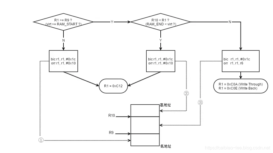
bne 1b上图内容就是进行页表项内容设置,其分支代码其实可以写成如下:
/* 若配置了 CPU D-cache 为直写方式,则 CB_BITS 的值是 0x08;否则(回写方式)是 0x0c
#ifdef CONFIG_CPU_DCACHE_WRITETHROUGH
#define CB_BITS 0x08
#else
#define CB_BITS 0x0c
#endif

/* $r_6$ = 0xA (CPU_DCACHE_WRITETHROUGH) 或 $r_6$ = 0xE (CPU_DCACHE_WRITEBACK)

/* case 1:  即0x0000 0000 ~ 0x3000 0000,r1 =0xC12
1:        cmp    r1, r9            @  virt < start of RAM
        bic    r1, r1, #0x1c        @ clear XN|U + C + B
        orrlo    r1, r1, #0x10        @ Set XN|U for non-RAM

/* case 2: 即0x3000 0000 ~ 0x4000 0000 即256M大小,r1 =0xC02
1:        cmp    r1, r9            @ if virt > start of RAM
        cmphs    r10, r1            @   && end of RAM > virt
        bic    r1, r1, #0x1c        @ clear XN|U + C + B
        orrhs    r1, r1, r6        @ set RAM section settings

/* case 3: 即0x4000 0000 ~ 0xFFFF FFFF,r1 =0xC12
1:        cmp    r1, r9            @ if virt > start of RAM
        cmphs    r10, r1            @   && end of RAM < virt
        bic    r1, r1, #0x1c        @ clear XN|U + C + B
        orrlo    r1, r1, #0x10        @ Set XN|U for non-RAM
对应的流程图如下
2.3 页表布局分析
内存布局如下:

(三)总结
1. 内核存在方式
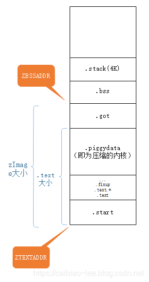
在我们进一步研究内核解压缩的时候,我们先来回顾下内核压缩后的内存分布。
内核压缩成gzip之间的过程我们不细致讨论,在这就被压缩成piggy.gzip了
然后我们由piggy.gzip再生成piggy.gzip.o。压缩后的piggy.gzip是以bin文件形式存放在piggy.gzip.o中的。
.section .piggydata,#alloc
.globl input_data
input_data:
.incbin "arch/arm/boot/compressed/piggy.gzip"
.globl input_data_end
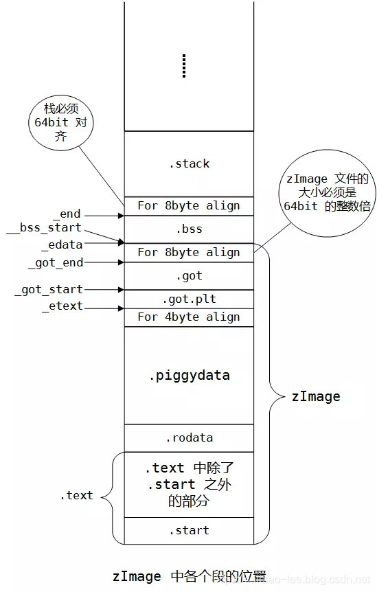
input_data_end:此时,piggy.gzip.o在链接地址布局是由arch/arm/boot/compressed/vmlinux.lds指定的,如下:
.text : {
    _start = .;
    *(.start)
    *(.text)
    *(.text.*)
    *(.fixup)
    *(.gnu.warning)
    *(.rodata)
    *(.rodata.*)
    *(.glue_7)
    *(.glue_7t)
    *(.piggydata)
    . = ALIGN(4);
  }
在内存图中显示如下:
2. 解压
2.1 是否覆盖
我们分析kernel解压是否会被覆盖需要知道两个地址:
内核被解压地址-16KB,这里是确保页表项不被覆盖
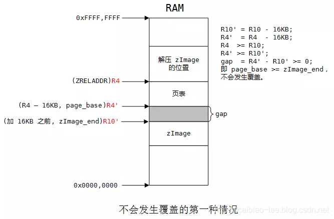
wont_overwrite地址,如果程序执行到这里,不会覆盖,就会去执行wont_overwrite,wont_overwrite标号是紧接着现在执行位置的,所以此处也不能被覆盖
2.2 覆盖处理
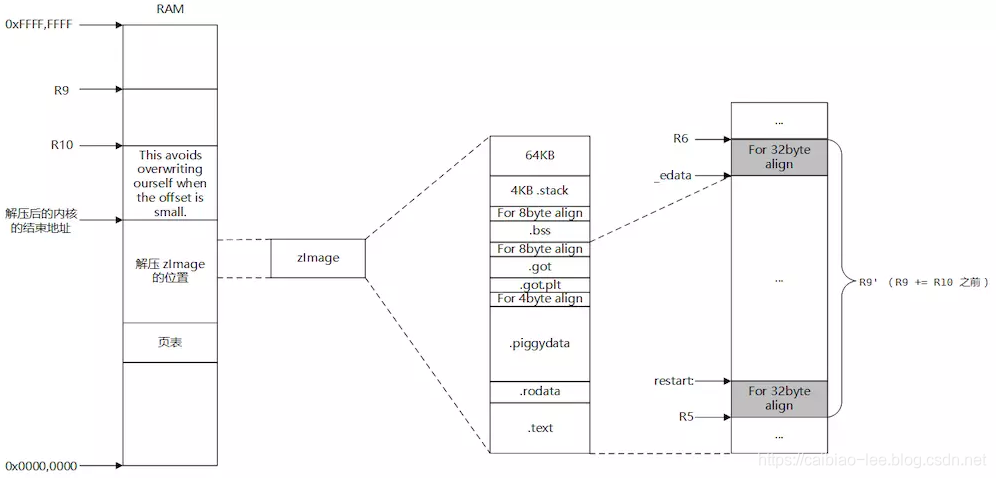
在分析前我们先加一张区域分布图:
现在进行覆盖处理:
File: /arch/arm/boot/compressed/head.S
         add    r10, r10, #((reloc_code_end - restart + 256) & ~255)
         bic    r10, r10, #255
此处R10=解压后的内核的结束地址+[(reloccodeend−restart)向上256字节对齐],再进行 256 字节对齐。
选定了复制范围,进行32byte对齐。
/* Get start of code we want to copy and align it down. */
        adr    r5, restart
        bic    r5, r5, #31
    ...
    ...
    sub    r9, r6, r5        @ size to copy
        add    r9, r9, #31        @ rounded up to a multiple
        bic    r9, r9, #31        @ ... of 32 bytes
        add    r6, r9, r5
        add    r9, r9, r10

1:        ldmdb    r6!, {r0 - r3, r10 - r12, lr}
        cmp    r6, r5
        stmdb    r9!, {r0 - r3, r10 - r12, lr}
        bhi    1b

    /* Preserve offset to relocated code. */
        sub    r6, r9, r6

#ifndef CONFIG_ZBOOT_ROM
        /* cache_clean_flush may use the stack, so relocate it * /
        add    sp, sp, r6
#endif
因为我们现在执行位置处于标号处,标号之前代码已经执行过,所以不用进行拷贝,拷贝的大小为R9 = 标号restart~zImage结束。拷贝分布图如下:
执行完拷贝后,内存分布如下:
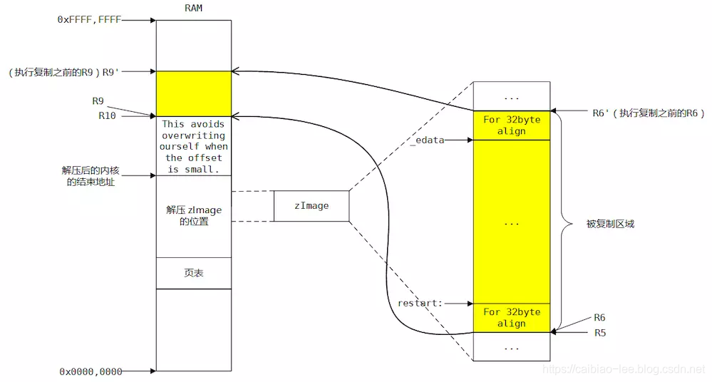
计算 “relocate_from 的起始地址”(R6) 到 “relocate_to 的起始地址”(R9) 之间的偏移量保存到 R6 中;并据此修改 SP 的值,从而完成了对栈的重定位。

刷新缓存这里就不再分析,然后就跳转到新的restart开始执行,此时就肯定能执行wont_overwrite:
badr    r0, restart
add    r0, r0, r6
mov    pc, r0
在wont_overwrite再调用decompress_kernel函数来进行内核解压,解压到地址R4:
File: /arch/arm/boot/compressed/head.S
475|         mov    r0, r4          @ R4 = ZRELADDR, 解压起始地址
476|         mov    r1, sp            @ malloc space above stack
477|         add    r2, sp, #0x10000    @ 64k max
478|         mov    r3, r7          @ r7  = architecture ID
479|         bl    decompress_kernel
解压完成后,在刷新缓存之类的操作,最后就跳转到内核来执行:
File: /arch/arm/boot/compressed/head.S
__enter_kernel:
         mov    r0, #0            @ must be 0
  ARM(        mov    pc, r4    )        @ call kernel
  THUMB(        bx    r4    )        @ entry point is always ARM
看了上面的源码,可能就算是分析过了也是比较模糊的,通过下面的一个代码流程图,大家就可以清楚的了解内核自解压的全过程了:
参考内容:
《linux 內核自解压》
http://www.404bbug.com/archive/?tag=Linux
《Linux内核源码分析--内核启动之(1)zImage自解压过程(Linux-3.0 ARMv7)》
http://blog.chinaunix.net/uid-20543672-id-3018233.html
《Linux内核DTB文件启动的几种方式》
https://www.cnblogs.com/iot-yun/p/11403498.html
linux arm 内核解压缩过程(注释)
https://blog.csdn.net/wyt357359/article/details/86669919
