实验 2-2 帧中继配置
学习目标
掌握用户边缘设备(CE)上帧中继接口的配置方法
掌握Hub-Spoke网络中RIP的配置方法
掌握Hub-Spoke(NBMA)网络中OSPF的配置方法
掌握点到多点网络中OSPF的配置方法
场景
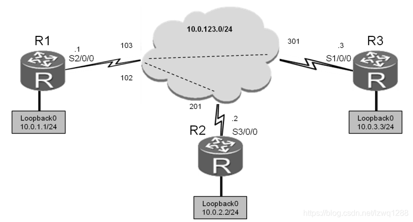
企业的总部和部分分支之间仍使用帧中继网络互连,作为企业的网络管理员,您需要在总部和分支的边缘路由器上配置帧中继功能,并配置本地DLCI与IP地址间的映射。
操作步骤
步骤一. 实验环境准备
如果本任务中您使用的是空配置设备,需要从步骤1开始配置,然后跳过步
骤2。如果使用的设备包含上一个实验的配置,请直接从步骤2开始配置。
system-view
Enter system view, return user view with Ctrl+Z.
[Huawei]sysname R1
system-view
Enter system view, return user view with Ctrl+Z.
[Huawei]sysname R2
system-view
Enter system view, return user view with Ctrl+Z.
[Huawei]sysname R3
步骤二. 清除设备上原有的配置
关闭三台路由器上HDLC和PPP封装的所有的串行接口。
[R1]interface Serial 1/0/0
[R1-Serial1/0/0]shutdown
[R2]interface Serial 1/0/0
[R2-Serial1/0/0]shutdown
[R2-Serial1/0/0]interface Serial 2/0/0
[R2-Serial2/0/0]shutdown
[R3]interface Serial 2/0/0
[R3-Serial2/0/0]shutdown
步骤三. 配置帧中继封装
配置基本参数及IP地址等信息。手动指定本地DLCI与对端IP地址的映射关系。
本任务中,需要关闭逆向地址解析功能,并在fr map命令中指定broadcast参数,从而使得该映射上能够发送广播报文。
[R1]interface Serial 2/0/0
[R1-Serial2/0/0]link-protocol fr
Warning: The encapsulation protocol of the link will be changed. Continue? [Y/N]:y
[R1-Serial2/0/0]ip address 10.0.123.1 24
[R1-Serial2/0/0]undo fr inarp
[R1-Serial2/0/0]fr map ip 10.0.123.2 102 broadcast
[R1-Serial2/0/0]fr map ip 10.0.123.3 103 broadcast
[R1-Serial2/0/0]interface loopback 0
[R1-LoopBack0]ip address 10.0.1.1 24
[R2]interface Serial 3/0/0
[R2-Serial3/0/0]link-protocol fr
Warning: The encapsulation protocol of the link will be changed. Continue? [Y/N]:y
[R2-Serial3/0/0]ip address 10.0.123.2 24
[R2-Serial3/0/0]undo fr inarp
[R2-Serial3/0/0]fr map ip 10.0.123.1 201 broadcast
[R2-Serial3/0/0]interface loopback 0
[R2-LoopBack0]ip address 10.0.2.2 24
[R3]interface Serial 1/0/0
[R3-Serial1/0/0]link-protocol fr
Warning: The encapsulation protocol of the link will be changed. Continue? [Y/N]:y
[R3-Serial1/0/0]ip address 10.0.123.3 24
[R3-Serial1/0/0]undo fr inarp
[R3-Serial1/0/0]fr map ip 10.0.123.1 301 broadcast
[R3-Serial1/0/0]interface loopback 0
[R3-LoopBack0]ip address 10.0.3.3 24
配置完成后,检测网络的连通性。
ping 10.0.123.2
查看R1接口的帧中继封装信息。
display fr interface Serial 2/0/0
步骤四. 在 R1、R2 和 R3 间配置 RIPv2 协议
在R1、R2和R3上配置RIPv2协议。如果您是在完成HDLC/PPP实验后的基
础上继续配置的本实验,则网段10.0.0.0已经在RIP网络中宣告。在本任务中需要关闭自动汇聚功能。
同时需要注意的是,由于帧中继网络的特殊性,默认情况下,帧中继接口下
RIP的水平分割功能被关闭。在本实验中,不对其进行修改。
[R1]rip 1
[R1-rip-1]version 2
[R1-rip-1]network 10.0.0.0
[R1-rip-1]undo summary
[R2]rip 1
[R2-rip-1]version 2
[R2-rip-1]network 10.0.0.0
[R2-rip-1]undo summary
[R3]rip 1
[R3-rip-1]version 2
[R3-rip-1]network 10.0.0.0
[R3-rip-1]undo summary
在R1、R2和R3的路由表中查看已经学习到的路由。
display ip routing-table protocol rip
在R3上以环回接口IP地址为源地址测试网络连通性。
[R3]ping –a 10.0.3.3 10.0.1.1
测试如果在R3上以物理接口S2/0/0(10.0.123.3)为源地址发送的报文,
能否转发到R2的网段10.0.2.2上。
[R3]ping 10.0.2.2
上述检测结果表明,当串行接口为源接口时,R3无法与R2通信(反之亦然)。
通过如下步骤找出R3无法与R2通信的原因:
- 在R3的路由表中查找是否存在通往10.0.2.2地址的相关路由条目。
- 如果存在通往10.0.2.2地址的相关路由条目,查看下一跳IP地址。然后,
检测R3发送的报文能否到达该下一跳,并检测三层IP地址是否有与二层PVC
的正确映射。 - 如果R3发送的报文能够到达该下一跳,而且三层IP地址已经与二层PVC
有正确映射,则检测R1上是否存在通往10.0.2.2地址的可达路由,该路由的
下一跳是否可达,三层IP地址是否与二层PVC正确映射。 - 如果单向路径没有问题,再查看目标设备,检测R2上是否存在通往回应
报文目的IP地址的相关路由条目,路由的下一跳是否可达。 - 如果路由的下一跳不可达,但是有回应报文的目的IP地址(10.0.123.3)
的相关路由条目,则表明R2上虽然有通往该地址的路由,但是没有三层IP地
址与二层PVC的正确映射。
上述故障诊断过程的命令回显信息如下:
display ip routing-table
由此可以看出,由于三层IP地址没有与二层PVC的正确映射,导致R2发送的
报文无法到达10.0.123.3。
步骤五. 修改网络参数,开启 R2 和 R3 之间的连接
步骤4中的故障诊断结果表明,R2和R3通信失败是因为帧中继接口之间没有
配置虚拟电路。要解决这一问题,需要在R2和R3的帧中继接口之间配置IP地址与PVC的映射关系。
[R2]interface Serial 3/0/0
[R2-Serial3/0/0]fr map ip 10.0.123.3 201
[R3]interface Serial 1/0/0
[R3-Serial1/0/0]fr map ip 10.0.123.2 301
配置完IP地址和PVC之间的映射后,查看R2和R3上的IP地址与PVC映射表
并检测网络的连通性。
display fr lmi-info inter Serial 1/0/0
步骤六. 在 R1 和 R2 间配置 OSPF 协议
删除步骤2中的RIP配置和步骤3中在R2和R3间建立的帧中继映射。
[R1]undo rip 1
Warning: The RIP process will be deleted. Continue?[Y/N]y
[R2]interface Serial 3/0/0
[R2-Serial3/0/0]undo fr map ip 10.0.123.3 201
[R2-Serial3/0/0]quit
[R2]undo rip 1
Warning: The RIP process will be deleted. Continue?[Y/N]y
[R3]interface Serial 1/0/0
[R3-Serial1/0/0]undo fr map ip 10.0.123.2 301
[R3-Serial1/0/0]quit
[R3]undo rip 1
Warning: The RIP process will be deleted. Continue?[Y/N]y
在R1、R2和R3上配置单区域OSPF。
[R1]ospf 1 router-id 10.0.1.1
[R1-ospf-1]area 0
[R1-ospf-1-area-0.0.0.0]network 10.0.0.0 0.255.255.255
[R2]ospf 1 router-id 10.0.2.2
[R2-ospf-1]area 0
[R2-ospf-1-area-0.0.0.0]network 10.0.0.0 0.255.255.255
[R3]ospf 1 router-id 10.0.3.3
[R3-ospf-1]area 0
[R3-ospf-1-area-0.0.0.0]network 10.0.0.0 0.255.255.255
基本参数配置完成后,发现OSPF无法建立邻居邻接关系。原因是OSPF在帧
中继网络中的的网络类型默认为NBMA,这种情况下,OSPF不支持广播,因而无法主动发现邻居。
display ospf interface Serial 1/0/0 verbose
步骤七. 配置 NBMA 网络
在NBMA网络中OSPF只能单播发送hello消息,因此需要手动指定邻居才能
转发hello消息。此外,当R3是指定路由器(DR)时,由于R2不能通过R2和R1
间的PVC与DR建立OSPF邻接关系。这种情况下,只能将R1配置为DR。
[R1]ospf
[R1-ospf-1]peer 10.0.123.2
[R1-ospf-1]peer 10.0.123.3
[R1-ospf-1]interface Serial 2/0/0
[R1-Serial2/0/0]ospf dr-priority 255
[R2]ospf
[R2-ospf-1]peer 10.0.123.1
[R3]ospf
[R3-ospf-1]peer 10.0.123.1
你还可以将 R2 和 R3 的 DR 优先级配置为 0,使它们不参加 DR 选举。
display ospf interface Serial 2/0/0 verbose
OSPF Process 1 with Router ID 10.0.1.1
Interfaces
Interface: 10.0.123.1 (Serial2/0/0)
如果修改优先级后R1不是DR,执行以下命令重启所有路由器上的OSPF进
程,然后再次执行上一条display命令。
reset ospf process graceful-restart
查看路由表,确认整个帧中继网络已经成功运行了OSPF协议。
display ip routing-table
测试网络连通性。
ping -a 10.0.1.1 10.0.2.2
步骤八. 将 OSPF 网络类型配置为点到多点
还可以在帧中继网络上配置点到多点的OSPF网络类型。首先删除手动指定
邻居关系的配置命令。
[R1]ospf
[R1-ospf-1]undo peer 10.0.123.2
[R1-ospf-1]undo peer 10.0.123.3
[R2]ospf
[R2-ospf-1]undo peer 10.0.123.1
[R3]ospf
[R3-ospf-1]undo peer 10.0.123.1
然后在接口试图下,将网络类型修改为点到多点。
[R1]interface Serial 2/0/0
[R1-Serial2/0/0]ospf network-type p2mp
[R2]interface Serial 3/0/0
[R2-Serial3/0/0]ospf network-type p2mp
[R3]interface Serial 1/0/0
[R3-Serial1/0/0]ospf network-type p2mp
配置完成后,等待设备自动建立邻居关系,然后查看邻居关系和路由信息。
display ospf peer brief
在R3上检测网络的连通性。
ping -a 10.0.3.3 10.0.1.1
配置文件
[R1]display current-configuration
[V200R007C00SPC600]
sysname R1
interface Serial2/0/0
link-protocol fr
undo fr inarp
fr map ip 10.0.123.2 102 broadcast
fr map ip 10.0.123.3 103 broadcast
ip address 10.0.123.1 255.255.255.0
ospf network-type p2mp
ospf dr-priority 255
interface LoopBack0
ip address 10.0.1.1 255.255.255.0
ospf 1 router-id 10.0.1.1
area 0.0.0.0
network 10.0.0.0 0.255.255.255
user-interface con 0
authentication-mode password
set authentication password
cipher %
dD#}P<HzJ;Xs%X>hOkm!,.+Iq61QKK6tI}cc-;k_oC.+L,%
user-interface vty 0 4
return
[R2]display current-configuration
[V200R007C00SPC600]
sysname R2
interface Serial3/0/0
link-protocol fr
undo fr inarp
fr map ip 10.0.123.1 201 broadcast
ip address 10.0.123.2 255.255.255.0
ospf network-type p2mp
interface LoopBack0
ip address 10.0.2.2 255.255.255.0
ospf 1 router-id 10.0.2.2
area 0.0.0.0
network 10.0.0.0 0.255.255.255
user-interface con 0
authentication-mode password
set authentication password
cipher %
|nRPL^hr2IXi7LHDID!/,.%.8%h;3:,hXO2dk#ikaWI.(,%
user-interface vty 0 4
return
[R3]display current-configuration
[V200R007C00SPC600]
sysname R3
interface Serial1/0/0
link-protocol fr
undo fr inarp
fr map ip 10.0.123.1 301 broadcast
ip address 10.0.123.3 255.255.255.0
ospf network-type p2mp
interface LoopBack0
ip address 10.0.3.3 255.255.255.0
ospf 1 router-id 10.0.3.3
area 0.0.0.0
network 10.0.0.0 0.255.255.255
user-interface con 0
authentication-mode password
set authentication password
cipher %
W|KaTeX parse error: Expected 'EOF', got '}' at position 5: )M5D}̲v@bY^gK\;>QR,.*…%$
user-interface vty 0 4
return