linux kernel的主要特点之一就是运行在虚拟地址空间上,但是怎么才能实现物理地址到虚拟地址空间的切换是本节关注的重点。本文使用的kernel版本为4.4。
bootloader跳转到kernel之前需要保证
MMU = off, D-cache = off, I-cache = dont care, r0 = 0, r1 = machine nr, r2 = atags or dtb pointer.
kernel启动阶段并没有使能MMU,因此在使能MMU之前,kernel需要将代码做到位置无关。
head.S
ENTRY(stext)
    ...
    @ ensure svc mode and all interrupts masked
    safe_svcmode_maskall r9                  //(1)

    mrc p15, 0, r9, c0, c0      @ get processor id
    bl  __lookup_processor_type     @ r5=procinfo r9=cpuid  // (2)
    movs    r10, r5             @ invalid processor (r5=0)?
 THUMB( it  eq )        @ force fixup-able long branch encoding
    beq __error_p           @ yes, error 'p'

    /*
     * r1 = machine no, r2 = atags or dtb,
     * r8 = phys_offset, r9 = cpuid, r10 = procinfo
     */
    bl  __vet_atags                        //(3)

    bl  __create_page_tables               //(4)

    /*
     * The following calls CPU specific code in a position independent
     * manner.  See arch/arm/mm/proc-*.S for details.  r10 = base of
     * xxx_proc_info structure selected by __lookup_processor_type
     * above.
     *
     * The processor init function will be called with:
     *  r1 - machine type
     *  r2 - boot data (atags/dt) pointer
     *  r4 - translation table base (low word)
     *  r5 - translation table base (high word, if LPAE)
     *  r8 - translation table base 1 (pfn if LPAE)
     *  r9 - cpuid
     *  r13 - virtual address for __enable_mmu -> __turn_mmu_on
     *
     * On return, the CPU will be ready for the MMU to be turned on,
     * r0 will hold the CPU control register value, r1, r2, r4, and
     * r9 will be preserved.  r5 will also be preserved if LPAE.
     */
    ldr r13, =__mmap_switched       @ address to jump to after   //(5)
                        @ mmu has been enabled
    badr    lr, 1f              @ return (PIC) address
    mov r8, r4              @ set TTBR1 to swapper_pg_dir
    ldr r12, [r10, #PROCINFO_INITFUNC]
    add r12, r12, r10
    ret r12
1:  b   __enable_mmu                         //(6)
ENDPROC(stext)
(1) 设置cpu工作模式,关中断
(2) 编译时cpu信息的定义在.proc.info.init段中,段定义如下:
arch/arm/kernel/vmlinux.lds.S
#define PROC_INFO                           \
    . = ALIGN(4);                           \
    VMLINUX_SYMBOL(__proc_info_begin) = .;              \
    *(.proc.info.init)                      \
    VMLINUX_SYMBOL(__proc_info_end) = .;
编译时会将proc-v7.S下的CPU信息按照宏定义__v7_proc的格式存储在.proc.info.init段中,下面只列了__v7_ca5mp_proc_info,__v7_ca7mp_proc_info和__v7_proc_info信息,其中__v7_ca7mp_proc_info对应的是我的平台中的cortext-A7,还有别的CPU在此处省略了。
arch/arm/mm/proc-v7.S
    .section ".proc.info.init", #alloc

    /*
     * Standard v7 proc info content
     */
.macro __v7_proc name, initfunc, mm_mmuflags = 0, io_mmuflags = 0, hwcaps = 0, proc_fns = v7_processor_functions
    ALT_SMP(.long   PMD_TYPE_SECT | PMD_SECT_AP_WRITE | PMD_SECT_AP_READ | \
            PMD_SECT_AF | PMD_FLAGS_SMP | \mm_mmuflags)
    ALT_UP(.long    PMD_TYPE_SECT | PMD_SECT_AP_WRITE | PMD_SECT_AP_READ | \
            PMD_SECT_AF | PMD_FLAGS_UP | \mm_mmuflags)
    .long   PMD_TYPE_SECT | PMD_SECT_AP_WRITE | \
        PMD_SECT_AP_READ | PMD_SECT_AF | \io_mmuflags
    initfn  \initfunc, \name
    .long   cpu_arch_name
    .long   cpu_elf_name
    .long   HWCAP_SWP | HWCAP_HALF | HWCAP_THUMB | HWCAP_FAST_MULT | \
        HWCAP_EDSP | HWCAP_TLS | \hwcaps
    .long   cpu_v7_name
    .long   \proc_fns
    .long   v7wbi_tlb_fns
    .long   v6_user_fns
    .long   v7_cache_fns
.endm

    /*
     * ARM Ltd. Cortex A5 processor.
     */
    .type   __v7_ca5mp_proc_info, #object
__v7_ca5mp_proc_info:
    .long   0x410fc050
    .long   0xff0ffff0
    __v7_proc __v7_ca5mp_proc_info, __v7_ca5mp_setup
    .size   __v7_ca5mp_proc_info, . - __v7_ca5mp_proc_info
...

    /*
     * ARM Ltd. Cortex A7 processor.
     */
    .type   __v7_ca7mp_proc_info, #object
__v7_ca7mp_proc_info:
    .long   0x410fc070
    .long   0xff0ffff0
    __v7_proc __v7_ca7mp_proc_info, __v7_ca7mp_setup
    .size   __v7_ca7mp_proc_info, . - __v7_ca7mp_proc_info
...
    /*
     * Match any ARMv7 processor core.
     */
    .type   __v7_proc_info, #object
__v7_proc_info:
    .long   0x000f0000      @ Required ID value
    .long   0x000f0000      @ Mask for ID
    __v7_proc __v7_proc_info, __v7_setup
    .size   __v7_proc_info, . - __v7_proc_info
lookup_processor_type前3行汇编得到了虚拟地址与物理地址间的差值,后面根据此差值和链接的虚拟地址得出了物理地址,在MMU使能之前都只能通过这种方法来使用链接地址(虚拟地址)。这三行解释如下:
adr r3, __lookup_processor_type_data //adr是将基于PC相对偏移的地址值或基于寄存器相对地址值读取的伪指令,所以r3中得到的是PC加上一个偏移量,此时PC是物理地址,r3得到的也是物理地址。而__lookup_processor_type_data的物理地址中实际存储的是__lookup_processor_type_data的链接地址,因为编译时肯定是按照虚拟地址进行编译的。
ldmia r3, {r4 - r6} //获取[r3], [r3+4], [r3+8]内存地址的变量到r4,r5,r6。
此时r4中存的是__lookup_processor_type_data的链接地址(虚拟地址)。
sub r3 ,r3 ,r4 // r3中得到的是物理地址与虚拟地址的偏移。
所以,r5,r6中得到的就是__proc_info_begin和__proc_info_end的物理地址。
__lookup_processor_type:
    adr r3, __lookup_processor_type_data
    ldmia   r3, {r4 - r6}
    sub r3, r3, r4          @ get offset between virt&phys
    add r5, r5, r3          @ convert virt addresses to
    add r6, r6, r3          @ physical address space
1:  ldmia   r5, {r3, r4}            @ value, mask
    and r4, r4, r9          @ mask wanted bits
    teq r3, r4
    beq 2f
    add r5, r5, #PROC_INFO_SZ       @ sizeof(proc_info_list)
    cmp r5, r6
    blo 1b
    mov r5, #0              @ unknown processor
2:  ret lr
ENDPROC(__lookup_processor_type)

/*
 * Look in <asm/procinfo.h> for information about the __proc_info structure.
 */
    .align  2
    .type   __lookup_processor_type_data, %object
__lookup_processor_type_data:
    .long   .
    .long   __proc_info_begin
    .long   __proc_info_end
    .size   __lookup_processor_type_data, . - __lookup_processor_type_data
根据cpuid,查找得到对应的cpu信息。cpu信息使用如下结构体:
struct proc_info_list {
    unsigned int        cpu_val;
    unsigned int        cpu_mask;
    unsigned long       __cpu_mm_mmu_flags; /* used by head.S */
    unsigned long       __cpu_io_mmu_flags; /* used by head.S */
    unsigned long       __cpu_flush;        /* used by head.S */
    const char      *arch_name;
    const char      *elf_name;
    unsigned int        elf_hwcap;
    const char      *cpu_name;
    struct processor    *proc;
    struct cpu_tlb_fns  *tlb;
    struct cpu_user_fns *user;
    struct cpu_cache_fns    *cache;
};
(3) 对r2中存储的atags进行检查,本文中r2中是传递来的dtb的地址,检查是否有OF_DT_MAGIC头。
arch/arm/kernel/head-common.S
__vet_atags:
    tst r2, #0x3            @ aligned?
    bne 1f

    ldr r5, [r2, #0]
#ifdef CONFIG_OF_FLATTREE
    ldr r6, =OF_DT_MAGIC        @ is it a DTB?
    cmp r5, r6
    beq 2f
#endif
    cmp r5, #ATAG_CORE_SIZE     @ is first tag ATAG_CORE?
    cmpne   r5, #ATAG_CORE_SIZE_EMPTY
    bne 1f
    ldr r5, [r2, #4]
    ldr r6, =ATAG_CORE
    cmp r5, r6
    bne 1f

2:  ret lr              @ atag/dtb pointer is ok

1:  mov r2, #0
    ret lr
ENDPROC(__vet_atags)
(4) 创建页表,本小节的重点,关系到物理地址空间到虚拟地址的切换。

__create_page_tables:
    pgtbl   r4, r8              @ page table address   //(a)

    /*
     * Clear the swapper page table
     */
    mov r0, r4
    mov r3, #0
    add r6, r0, #PG_DIR_SIZE
1:  str r3, [r0], #4                                         //(b)
    str r3, [r0], #4
    str r3, [r0], #4
    str r3, [r0], #4
    teq r0, r6
    bne 1b


    ldr r7, [r10, #PROCINFO_MM_MMUFLAGS] @ mm_mmuflags    //(c)

    /*
     * Create identity mapping to cater for __enable_mmu.
     * This identity mapping will be removed by paging_init().
     */
    adr r0, __turn_mmu_on_loc
    ldmia   r0, {r3, r5, r6}
    sub r0, r0, r3          @ virt->phys offset
    add r5, r5, r0          @ phys __turn_mmu_on
    add r6, r6, r0          @ phys __turn_mmu_on_end
    mov r5, r5, lsr #SECTION_SHIFT
    mov r6, r6, lsr #SECTION_SHIFT

1:  orr r3, r7, r5, lsl #SECTION_SHIFT  @ flags + kernel base
    str r3, [r4, r5, lsl #PMD_ORDER]    @ identity mapping
    cmp r5, r6
    addlo   r5, r5, #1          @ next section
    blo 1b

    /*
     * Map our RAM from the start to the end of the kernel .bss section.
     */
    add r0, r4, #PAGE_OFFSET >> (SECTION_SHIFT - PMD_ORDER)                   //(d)
    ldr r6, =(_end - 1)
    orr r3, r8, r7
    add r6, r4, r6, lsr #(SECTION_SHIFT - PMD_ORDER)
1:  str r3, [r0], #1 << PMD_ORDER
    add r3, r3, #1 << SECTION_SHIFT
    cmp r0, r6
    bls 1b

    /*
     * Then map boot params address in r2 if specified.
     * We map 2 sections in case the ATAGs/DTB crosses a section boundary.
     */
    mov r0, r2, lsr #SECTION_SHIFT                                                    //(e)
    movs    r0, r0, lsl #SECTION_SHIFT
    subne   r3, r0, r8
    addne   r3, r3, #PAGE_OFFSET
    addne   r3, r4, r3, lsr #(SECTION_SHIFT - PMD_ORDER)
    orrne   r6, r7, r0
    strne   r6, [r3], #1 << PMD_ORDER
    addne   r6, r6, #1 << SECTION_SHIFT
    strne   r6, [r3]
(a) 获取页表首地址
    .macro  pgtbl, rd, phys
    add \rd, \phys, #TEXT_OFFSET
    sub \rd, \rd, #PG_DIR_SIZE
    .endm
r8=0x80000000,pgtbl宏获取TEXT_OFFSET, 即地址0x80008000之下16K的地址空间作为页表空间,arm页表项每项占4bytes,1项可映射1M空间,4G虚拟地址空间一共需要4096项,因此一共占用4*4096字节。
    pgtbl   r4, r8
c000808c:   e2884902    add r4, r8, #32768  ; 0x8000
c0008090:   e2444901    sub r4, r4, #16384  ; 0x4000
r4 =0x80000000 + 0x4000
(b) 将页表内存空间清零,即将0x80004000~0x80008000的空间清零。
(c) 为__turn_mmu_on建立identify map,即一致性映射
首先从处理器的procinfo结构中获取__cpu_mm_mmu_flags参数保存在r7中,然后取__turn_mmu_on_loc处的地址保存到r0中,然后使用前文中所述通过减去物理地址与虚拟地址偏移的方法,获得__trun_mmu_on和__trun_mmu_on_end的实际物理地址,并保存到 r5和r6寄存器中。
__turn_mmu_on_loc:
    .long   .
    .long   __turn_mmu_on
    .long   __turn_mmu_on_end
因1页表项映射1M空间,所以SECTION_SHIFT为20,r5和r6中的值右移20位,得到了__trun_mmu_on和__trun_mmu_on_end的物理基地址。
这里将r5左移20位后或上r7中的标识位,然后将这个描述符写到页表中对应的项中去。页表地址 = 映射物理基址 << 2,映射基地址为r5,r4为页表基地址,得到如下关系:
[r4 + r5<<2] = r3
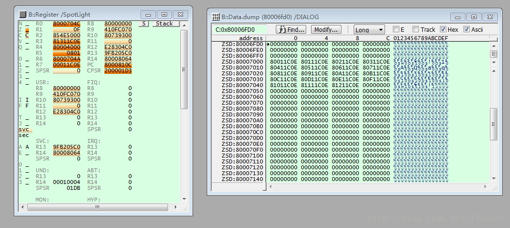
在我的平台dump相关寄存器:
r4=0x80004000 r5=0x801 r6=0x801 r3=0x80111c0e r7=0x00011c0e
[0x80006004] = 0x8011c0e
可以通过页表项0x8011c0e中0x801得到__turn_mmu_on函数所在的物理地址段0x80100000,物理地址与虚拟地址一致,即一致性映射建立完成。
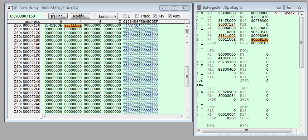
(d) 建立kernel image map,与(c)类似,不详述,在我的平台结果如下:
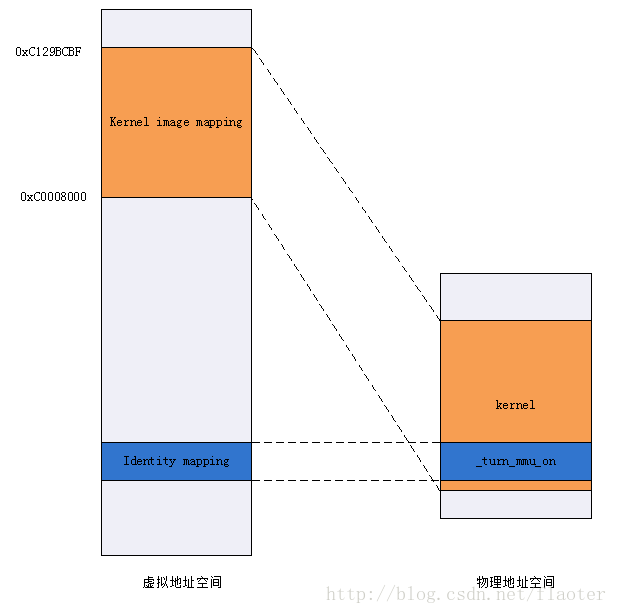
end = 0xC129BCBF start=0xc0008000, kernel image占用19M空间, 使用了19个页表项。
从图中可知,通过页表项0x8011c0e中0x801可得到kernel image的起始地址0xc0008000所在的物理地址段,通过最后一个页表项0x8121c0e中0x812可得到kernel image的终止地址0xC129BCBF所在的物理地址段。真实的虚拟地址空间到物理地址空间的映射,kernel image映射建立完成。
此时的虚拟地址空间与物理地址空间的映射如下图所示,identity mapping和kernel image mapping也是理解本小节内容的关键。
(e)建立atags启动参数map,也是一个真实的虚拟地址到物理地址的映射
到此,__create_page_tables完成。
(5)保存__mmap_switched函数的虚拟地址到r13中,它是MMU开启后的第一个要跳转运行的虚拟地址。保存”b __enable_mmu”的地址到lr作为返回地址,然后保存r4中的页表物理地址到r8寄存其中,最后就跳转到架构相关的处理器初始化函数中执行初始化,为开启MMU做准备工作;
PROCINFO_INITFUNC定义如下,因此执行的处理器初始化函数就是__cpu_flush函数。
DEFINE(PROCINFO_INITFUNC, offsetof(struct proc_info_list, __cpu_flush));再将(2)中proc.info.init段中自己cpu的proc_info_list复制如下,可知__cpu_flush对应的cortextA7中的__v7_ca7mp_proc_info函数。该函数主要是invalidate cache, TLB等为使能MMU做最后准备,此处不进行详述了。
    .type   __v7_proc_info, #object
__v7_proc_info:
    .long   0x000f0000      @ Required ID value
    .long   0x000f0000      @ Mask for ID
    __v7_proc __v7_proc_info, __v7_setup
    .size   __v7_proc_info, . - __v7_proc_info
(6)__enbale_mmu执行之前的寄存器如下代码中的注释所示,根据内核配置通过r0操作CP15 CR1配置。
/*
 * Setup common bits before finally enabling the MMU.  Essentially
 * this is just loading the page table pointer and domain access
 * registers.  All these registers need to be preserved by the
 * processor setup function (or set in the case of r0)
 *
 *  r0  = cp#15 control register
 *  r1  = machine ID
 *  r2  = atags or dtb pointer
 *  r4  = TTBR pointer (low word)
 *  r5  = TTBR pointer (high word if LPAE)
 *  r9  = processor ID
 *  r13 = *virtual* address to jump to upon completion
 */
__enable_mmu:
#if defined(CONFIG_ALIGNMENT_TRAP) && __LINUX_ARM_ARCH__ < 6
    orr r0, r0, #CR_A
#else
    bic r0, r0, #CR_A
#endif
#ifdef CONFIG_CPU_DCACHE_DISABLE
    bic r0, r0, #CR_C
#endif
#ifdef CONFIG_CPU_BPREDICT_DISABLE
    bic r0, r0, #CR_Z
#endif
#ifdef CONFIG_CPU_ICACHE_DISABLE
    bic r0, r0, #CR_I
#endif
#ifdef CONFIG_ARM_LPAE
    mcrr    p15, 0, r4, r5, c2      @ load TTBR0
#else
    mov r5, #DACR_INIT
    mcr p15, 0, r5, c3, c0, 0       @ load domain access register
    mcr p15, 0, r4, c2, c0, 0       @ load page table pointer
#endif
    b   __turn_mmu_on
ENDPROC(__enable_mmu)
寄存器每一位定义如下:
#define CR_M    (1 << 0)    /* MMU enable               */
#define CR_A    (1 << 1)    /* Alignment abort enable       */
#define CR_C    (1 << 2)    /* Dcache enable            */
#define CR_W    (1 << 3)    /* Write buffer enable          */
#define CR_P    (1 << 4)    /* 32-bit exception handler     */
#define CR_D    (1 << 5)    /* 32-bit data address range        */
#define CR_L    (1 << 6)    /* Implementation defined       */
#define CR_B    (1 << 7)    /* Big endian               */
#define CR_S    (1 << 8)    /* System MMU protection        */
#define CR_R    (1 << 9)    /* ROM MMU protection           */
#define CR_F    (1 << 10)   /* Implementation defined       */
#define CR_Z    (1 << 11)   /* Implementation defined       */
#define CR_I    (1 << 12)   /* Icache enable            */
...
然后调用__trun_mmu_on置上MMU enable位,MMU就开启了。
注意一下置位操作是在”movc p0.c1, r0, #0”语句完成的,后面的一条语句的PC已经是虚拟地址了,但是因为对此函数进行了一致性映射,物理地址与虚拟地址一致,所以才能正确得取到MMU开启后的后一行指令。后面的操作就是将r15赋给PC,r15就是kernel image mapping中映射的地址空间了,此处是__mmap_switched的地址。
/*
 * Enable the MMU.  This completely changes the structure of the visible
 * memory space.  You will not be able to trace execution through this.
 *
 *  r0  = cp#0 control register
 *  r15 = *virtual* address to jump to upon completion
 */
__turn_mmu_on:
    mov r0, r0
    movc    p0.c1, r0, #0           @ write control reg
    nop                 @ fetch inst by phys addr
    mov pc, r15
    nop8                    @ fetch inst by phys addr
ENDPROC(__turn_mmu_on)
开启MMU后,接下来执行__mmap_switched,该函数是kernel image mapping的虚拟地址空间了,就是我们常见到的0xC0000000之后的地址了。__mmap_switched主要执行C环境准备工作,之后就可以跳到C环境运行了。