软件IIC和硬件IIC
IIC协议:I2C通讯协议,引脚少,硬件实现简单,可扩展性强,不需要USART、CAN等通讯协议的外部收发设备,现在被广泛地使用在系统内多个集成电路(IC)间的通讯。
1、软件IIC:软件I2C一般是用GPIO管脚,用软件控制管脚状态以模拟I2C通信波形。
2、硬件IIC:所谓硬件I2C对应芯片上的I2C外设,有相应I2C驱动电路,其所使用的I2C管脚也是专用的。
区别在于硬件I2C的效率要远高于软件的,而软件I2C由于不受管脚限制,接口比较灵活。硬件IIC用法比较复杂,模拟IIC的流程更清楚一些。
实验过程
实验目的
设计程序实现每隔2秒钟采集一次温湿度数据,并通过串口发送到上位机
代码实现
#include "stm32f10x.h"
#include "stm32f10x_usart.h"
#include "misc.h"
#include "stdio.h"
#include "delay.h"
#include "bsp_i2c.h"
#include "ATH20.h"

void RCC_Configuration(void);
void GPIO_Configuration(void);

GPIO_InitTypeDef GPIO_InitStructure;

#pragma import(__use_no_semihosting)
struct __FILE
{


	int handle;

};
FILE __stdout;
_sys_exit(int x)
{


	x = x;
}
int fputc(int ch, FILE *f)
{


	while(USART_GetFlagStatus(USART1,USART_FLAG_TC)==RESET);
    USART_SendData(USART1,(uint8_t)ch);
	return ch;
}

void uart_init(u32 bound)
{


    //GPIO¶Ë¿ÚÉèÖÃ
    GPIO_InitTypeDef GPIO_InitStructure;
	USART_InitTypeDef USART_InitStructure;

	RCC_APB2PeriphClockCmd(RCC_APB2Periph_USART1|RCC_APB2Periph_GPIOA, ENABLE);	//ʹÄÜUSART1£¬GPIOAʱÖÓ
 	USART_DeInit(USART1);  //¸´Î»´®¿Ú1
    //USART1_TX   PA.9
    GPIO_InitStructure.GPIO_Pin = GPIO_Pin_9; //PA.9
    GPIO_InitStructure.GPIO_Speed = GPIO_Speed_50MHz;
    GPIO_InitStructure.GPIO_Mode = GPIO_Mode_AF_PP;	//¸´ÓÃÍÆÍìÊä³ö
    GPIO_Init(GPIOA, &GPIO_InitStructure); //³õʼ»¯PA9

    //USART1_RX	  PA.10
    GPIO_InitStructure.GPIO_Pin = GPIO_Pin_10;
    GPIO_InitStructure.GPIO_Mode = GPIO_Mode_IN_FLOATING;//¸¡¿ÕÊäÈë
    GPIO_Init(GPIOA, &GPIO_InitStructure);  //³õʼ»¯PA10

    //USART ³õʼ»¯ÉèÖÃ
	USART_InitStructure.USART_BaudRate = bound;//Ò»°ãÉèÖÃΪ9600;
	USART_InitStructure.USART_WordLength = USART_WordLength_8b;//×Ö³¤Îª8λÊý¾Ý¸ñʽ
	USART_InitStructure.USART_StopBits = USART_StopBits_1;//Ò»¸öֹͣλ
	USART_InitStructure.USART_Parity = USART_Parity_No;//ÎÞÆæżУÑéλ
	USART_InitStructure.USART_HardwareFlowControl = USART_HardwareFlowControl_None;//ÎÞÓ²¼þÊý¾ÝÁ÷¿ØÖÆ
	USART_InitStructure.USART_Mode = USART_Mode_Rx | USART_Mode_Tx;	//ÊÕ·¢Ä£Ê½

    USART_Init(USART1, &USART_InitStructure); //³õʼ»¯´®¿Ú

    USART_Cmd(USART1, ENABLE);                    //ʹÄÜ´®¿Ú
}

int main(void)
{


    uint8_t ret = 0;
    float P,T,ALT;
    uint32_t CT_data[2];
	int  c1,t1;
    uint8_t LED_Stat = 0;

    RCC_Configuration();					   	//ÉèÖÃϵͳʱÖÓ
    GPIO_Configuration();					    //IO¿ÚÉè
    I2C_Bus_Init();

    uart_init(115200);

   ret = ATH20_Init();
    if(ret == 0)
    {


        printf("ATH20´«¸ÐÆ÷³õʼ»¯´íÎó\n");
        while(1);
    }


    while(1)
    {


        /* ¶ÁÈ¡ ATH20 ´«¸ÐÆ÷Êý¾Ý*/
        while(ATH20_Read_Cal_Enable() == 0)
        {


            ATH20_Init();//Èç¹ûΪ0ÔÙʹÄÜÒ»´Î
            SoftDelay_ms(30);
        }
        ATH20_Read_CTdata(CT_data);  //¶ÁȡζȺÍʪ¶È
        c1 = CT_data[0] * 1000 / 1024 / 1024;  //¼ÆËãµÃµ½Êª¶ÈÖµ£¨·Å´óÁË10±¶,Èç¹ûc1=523£¬±íʾÏÖÔÚʪ¶ÈΪ52.3%£©
        t1 = CT_data[1] * 200 *10 / 1024 / 1024 - 500;//¼ÆËãµÃµ½Î¶ÈÖµ£¨·Å´óÁË10±¶£¬Èç¹ût1=245£¬±íʾÏÖÔÚζÈΪ24.5¡æ£©

        printf("AHT20ÎÂʪ¶È´«¸ÐÆ÷²âÊÔÊý¾Ý:\n");
        printf("ζÈ: %d.%d ¡æ\n",(t1/10),(t1%10));
        printf("ʪ¶È: %d.%d %%\n",(c1/10),(c1%10));
        printf("\n");


        SoftDelay_ms(1000);//ÿ¸ôÁ½Ãë¶ÁÒ»´ÎÊý

        if(LED_Stat == 0)
        {


            LED_Stat = 1;
            GPIO_ResetBits(GPIOC, GPIO_Pin_2);
        }
        else
        {


            LED_Stat = 0;
            GPIO_SetBits(GPIOC, GPIO_Pin_2);
        }
    }
}

void RCC_Configuration(void)
{


  SystemInit();

  RCC_APB2PeriphClockCmd(RCC_APB2Periph_AFIO, ENABLE);
  RCC_APB2PeriphClockCmd(RCC_APB2Periph_GPIOA | RCC_APB2Periph_GPIOB | RCC_APB2Periph_GPIOC
  						| RCC_APB2Periph_GPIOD| RCC_APB2Periph_GPIOE , ENABLE);
}

void GPIO_Configuration(void)
{


  GPIO_InitTypeDef GPIO_InitStructure;

  GPIO_InitStructure.GPIO_Pin = GPIO_Pin_2 | GPIO_Pin_4 | GPIO_Pin_5 | GPIO_Pin_7;				     //״̬LED1
  GPIO_InitStructure.GPIO_Mode = GPIO_Mode_Out_PP;			 //ͨÓÃÍÆÍìÊä³öģʽ
  GPIO_InitStructure.GPIO_Speed = GPIO_Speed_50MHz;			 //Êä³öģʽ×î´óËÙ¶È50MHz
  GPIO_Init(GPIOC, &GPIO_InitStructure);
}
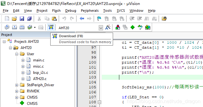
代码烧录
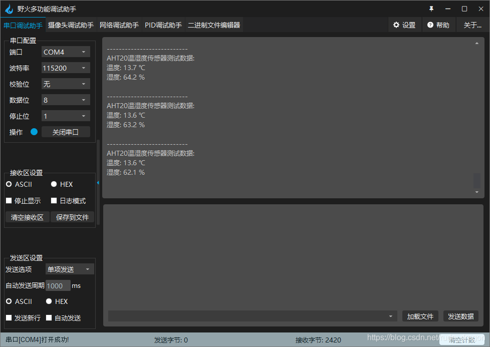
串口通信
打开串口,查看温湿度测试结果